

1 INTRODUCTION
Wet clutches are widely used in automotive and helicopter transmission systems due to their smooth engagement, compact structure, and long service life. The tribological behavior of friction pairs during engagement has been a persistent research focus in this field [1,2]. However, during operation, the combined effects of mechanical and thermal stresses cause internal stress distributions within the clutch plates to exceed the material’s yield limit, resulting in warping deformation. The altered clearance geometry between friction pairs under warped structures further impacts the engagement characteristics of wet clutches.
Extensive foundational research has been conducted on wet clutch engagement behavior. In oil film hydrodynamic modeling, Patir and Cheng [3] introduced a three-dimensional surface roughness factor into the Reynolds equations, proposing theories for shear flow factors and pressure flow factors. Beavers and Joseph [4] established a permeable wall sliding model based on Darcy’s law. Berger et al. [5] conducted finite element simulations of wet clutch engagement processes using the Beavers-Joseph slip model and flow factors, investigating the influence of material permeability on engagement characteristics. Jang and Khonsari [6] and Jang et al. [7] developed a modified Reynolds equation incorporating friction plate groove geometry and friction surface material properties, based on Patir’s flow factor theory and the mean Reynolds equation. They solved this using a dimensionless approach and combined it with the Greenwood-Williamson (G-W) contact model to determine wet clutch engagement characteristics, investigating the influence of factors like friction plate groove shape on engagement behavior. Zhang et al. [8] developed a coupled model for oil film pressure, applied pressure, and dynamic torque transmission based on the Patir-Cheng mean Reynolds equation and G-W elastic contact model. They employed a fourth-order Runge-Kutta method to solve the relationship between oil film thickness and speed difference. The study quantitatively analyzed the influence patterns of parameters such as pressure lag time, lubricant viscosity, and friction lining permeability on the engagement torque response of wet clutches. Huang et al. [9] addressed the squeeze phase of wet friction clutches by solving hydrodynamic pressure and load-bearing capacity using finite difference methods based on modified Reynolds equations and Kogut-Etsion (K-E) micro-asperity contact models. Jin et al. [10] enhanced the fluid-bearing model associated with the Reynolds equation in fluid-structure interaction dynamics research on wet clutch slip torque. This was achieved by modifying the Patir-Cheng mean flow model and introducing induced pressure to replace fluid pressure, thereby addressing variable viscosity effects.
In the field of roughness torque analysis, Greenwood and Williamson [11] proposed that the distribution of micro-asperities on rough surfaces approximates a Gaussian function based on Hertz contact theory and experimental data. They developed the G-W rough contact model by assuming the micro-asperities are hemispheres with a radius equal to their height. Majumdar and Bhushan [12] established the Majumdar-Bhushan (M-B) rough contact model based on fractal roughness parameters. This model proposes that as the contact area increases, micro-asperity contact undergoes a gradual transition from plastic to elastic behavior. Kogut and Etsion [13] proposed that micro-asperity contact transitions from elastic to plastic as contact area increases. Using finite element methods to study contact characteristics between rigid smooth plates and rough surfaces, they established the K-E rough contact model. Masjedi and Khonsari [14] developed a point-contact hybrid lubrication model based on modified Reynolds equations and the ZMC elastoplastic micro-asperity model, deriving formulas for central film thickness and micro-asperity load ratio. Wang et al. [15] considered lubricant centrifugal effects, friction material permeability, surface roughness, and the K-E model (micro-asperity contact model) to establish a coupled model of hydrodynamic oil film – rough contact – torque transmission. They quantitatively analyzed the influence of groove shape and depth on mating characteristics. Wu et al. [16] developed a microcontact thermodynamic model incorporating micro-asperity elastoplastic deformation based on elastohydrodynamic lubrication theory, deriving a composite friction coefficient formula that accounts for oil film shear and micro-asperity contact. Yang et al. [17] established a comprehensive model for grooved engagement characteristics based on Navier-Stokes equations and K-E rough contact theory, combining orthogonal experiments to clarify the synergistic influence of multiple parameters on torque. Bao et al. [18,19] analyzed the engagement process of multiple friction pairs in wet clutches by establishing axial and circumferential motion models. These studies provide support for oil film load-bearing capacity and friction torque analysis. However, most focus on flat friction pairs without considering gap asymmetry caused by warping deformation, failing to accurately describe oil film dynamic behavior under warping conditions. Existing warping studies primarily revolve around temperature effects, lacking precise descriptions of the engagement process for warped friction pairs.
In summary, while extensive research exists on the engagement characteristics and influencing factors of wet clutches, studies on the engagement characteristics of warped friction pairs remain scarce. Therefore, this paper establishes the mean Reynolds equation and K-E contact model, considering factors such as roughness based on the structural characteristics of the warped friction pair. It investigates the engagement characteristics of aviation wet clutches through a coupled analysis of the mechanical properties of warped clutch plates and examines the influence of factors such as clutch plate warpage and piston pressure on engagement characteristics.
2 METHODS AND MATERIALS
2.1 Analysis of the Clutch Engagement Process
During the engagement speed regulation process of wet friction clutches, conventional friction pairs are characterized by the presence of an interstitial oil film, which can be divided into the squeeze phase, mixed friction phase, and full rough friction phase. In contrast, warped friction pairs, due to their axial warping structure, exhibit non-negligible viscous forces within the clearance throughout the engagement process. Consequently, warped friction pairs only undergo the squeeze phase and mixed friction phase during engagement speed regulation, as illustrated in Fig. 1. Additionally, the engagement speed regulation process of wet friction clutches is characterized by the deformation of the warped dual steel plates, which can be divided into the non-contact phase, deformation phase, and plastic phase. During the non-contact phase, the contact force of asperities is negligible. In the deformation phase, the warped dual steel plates undergo deformation under axial force; in the plastic phase, the warped dual steel plates reach a critical deformation level, and their geometric shape remains unchanged.
2.2 Axial Motion Analysis
2.2.1 Dynamic Pressure Distribution of Oil Film Between Plates
Based on the friction stage during the engagement process of a wet clutch and the deformation stage of the warped dual steel plate, the following assumptions are proposed: the lubricating oil flows steadily between the friction pairs; the lubricating oil flows periodically and symmetrically within the clearance between the friction pairs; the dynamic pressure gradient of the lubricating oil film is zero in the direction of film thickness; the lubricating oil is an incompressible fluid; there is no relative velocity between the lubricating oil film and the friction pair surfaces; the velocity in the direction of oil film thickness between the friction pairs is neglected; the effect of mass forces on the lubricating oil film is neglected; and the oil groove structure of the friction plates is neglected.
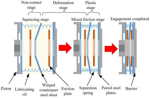
Fig. 1. Schematic diagram of the coupling speed regulation phase
Based on the above assumptions, combined with the N-S equation, the mass conservation equation, and the flow factor model [20,21], the Reynolds equation for lubricant flow between wet clutch friction pairs based on friction material permeability and other factors is derived, as shown in Eq. (1):
\begin{gathered}
\frac{1}{r}\frac{\partial}{\partial r}\left( r\left[ \varphi_r (1 + 3\chi) h^3 + 6\varphi_r \alpha \chi \sqrt{\phi_0} h^2 + 12\phi d \right]\frac{\partial p}{\partial r} \right) \\
\quad + \frac{1}{r}\frac{\partial}{\partial \theta}\left( \frac{1}{r}\left[ \varphi_\theta h^3 + 12\phi_0 d \right]\frac{\partial p}{\partial \theta} \right) = \\
= \frac{1}{r}\frac{\partial}{\partial r}\left( \frac{1}{10}\varphi_r \rho h^3 r^2 \left[ 3(1 + 5\chi)\omega_s^2 + 2(2 + 5\chi)\omega_s \omega_f + (3 + 5\chi)\omega_f^2 \right] \right) \\
\quad + 12\mu \frac{\partial h}{\partial t}
– 6\mu (\omega_s + \omega_f)\frac{\partial h}{\partial \theta}
+ 6\mu (\omega_s – \omega_f)\frac{\partial}{\partial \theta}(\sigma \varphi_s).
\end{gathered}
\tag{1}
\end{equation}$$
where χ is the Beaver-Joseph factor, α is the sliding coefficient, ϕ0 is the permeability of the friction lining material [m–2], d is the thickness of the friction lining [m], φr, φθ and φs represent the radial, circumferential pressure flow factor, and shear flow factor, respectively, h is the oil film thickness [m]; ρ is the lubricant density [kg/m3], ωs and ωf are the rotational speeds of the dual steel plate and friction plate [rad/s], respectively, μ is the lubricant viscosity [Pas], and σ is the root mean square of the combined surface roughness [m].
The finite difference method is used to solve the oil film dynamic pressure distribution model. Considering that the magnitudes of different physical quantities vary greatly, they are dimensionless. The dimensionless Reynolds equation for the clutch friction pair clearance is:
\begin{gathered}
\frac{1}{\bar r}\frac{\partial}{\partial \bar r}\left( \bar r\left[ \varphi_r (1 + 3\bar\chi)\bar h^3 + 6\varphi_r \alpha \bar\chi \sqrt{\bar\phi_0}\,\bar h^2 + 12\bar\phi\,\bar d \right]\frac{\partial \bar p}{\partial \bar r} \right) \\
\quad + \frac{1}{\bar r}\frac{\partial}{\partial \theta}\left( \frac{1}{\bar r}\left[ \varphi_\theta \bar h^3 + 12\bar\phi_0\,\bar d \right]\frac{\partial \bar p}{\partial \theta} \right) = \\
\frac{1}{\bar r}\frac{\partial}{\partial \bar r}\left( \frac{1}{10}\varphi_r \bar h^3 \bar r^2 \left[ 3(1 + 5\bar\chi)\bar\omega_s^2 + 2(2 + 5\bar\chi)\bar\omega_s \bar\omega_f + (3 + 5\bar\chi)\bar\omega_f^2 \right] \right) \\
\quad + 12\psi_1 \frac{\partial \bar h}{\partial t}
– 6\psi_2 (\bar\omega_s + \bar\omega_f)\frac{\partial \bar h}{\partial \theta}
+ 6\psi_3 (\bar\omega_s – \bar\omega_f)\frac{\partial \varphi_s}{\partial \theta}
\end{gathered}
\tag{2}
\end{equation}$$
The dimensionless parameters used in the equation are defined as follows: dimensionless radius \( \bar r = \frac{r}{r_2} \), dimensionless inner diameter \( \bar R_i = \frac{r_1}{r_2} \), dimensionless dynamic pressure \( \bar p = \frac{P}{P_s} \), dimensionless permeability \( \bar{\phi}_0 = \frac{\phi_0}{h_d^2} \), dimensionless liner thickness \( \bar d = \frac{d}{h_d} \), dimensionless oil film thickness \( \bar h = \frac{h}{h_d} \), dimensionless follower end angular velocity \( \bar{\omega}_f = \frac{\omega_f}{\omega_{tar}} \), dimensionless active tip angle velocity \( \bar{\omega}_s = \frac{\omega_s}{\omega_{tar}} \), dimensionless viscosity \( \bar{\mu} = \frac{\mu}{\mu_{40}} \), and coefficients \( \psi_1 = \frac{\rho r_2^2 \omega_{tar}^2}{P_s},\; \psi_2 = \frac{\mu_{40} r_2^2 \omega_{tar}}{P_s h_d^2},\; \psi_3 = \frac{\mu_{40} r_2^2 \sigma \omega_{tar}}{P_s h_d^3} \), where Ps is the stable piston pressure value [Pa], ωtar is the target clutch engagement speed [rad/s], μ40 is the viscosity of the lubricating oil at 40 °C [Pas], r1 and r2 are the inner radius and outer radius of the friction pair, respectively [m]; hd is the average oil film thickness [m].
The oil film bearing capacity between friction pairs can be expressed as:
F_v = \int_0^{2\pi} \int_{r_1}^{r_2} \left( \bar p \cdot P_s \cdot \bar r \cdot r_2 \right)\, dr\, d\theta .
\tag{3}
\end{equation}$$
2.2.2 Asperity Rough Contact Model
During the engagement process of a wet clutch in the mixed friction stage, the micro-protrusions on the dual steel plate and friction plate surfaces begin to contact and deform, generating rough friction torque. This affects the warping, deformation, and plastic deformation stages of the mating steel plate during the engagement speed regulation process of the wet clutch. Among the two rough surfaces, the friction plate surface has a higher roughness. The dual steel plate surface and the friction plate surface are equivalently modeled as a rigid smooth surface and an equivalent rough surface, as shown in Fig. 2.
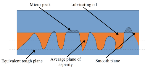
Fig. 2. Rough surface contact and its simplified model
By dividing the deformation process of a micro-protrusion into an elastic deformation stage, a stage where plastic deformation begins to appear, a stage where plastic deformation surrounds elastic deformation, and a stage of complete plastic deformation, we can obtain the dimensionless contact area and contact force on a rough surface [20], which can be expressed as:
\bar A_a = \pi \rho_a \sigma R_a \bar\delta_c \Big(
\int_{h_a}^{h_a + \bar\delta_c} I
+ 0.93 \int_{h_a + \bar\delta_c}^{h_a + 6\bar\delta_c} I^{1.136}
+ 0.094 \int_{h_a + 6\bar\delta_c}^{h_a + 110\bar\delta_c} I^{1.146}
+ 2 \int_{h_a + 110\bar\delta_c}^{\infty} I
\Big),
\tag{4}
\end{equation}$$
\bar F_a = \frac{2}{3} K \pi \rho_a \sigma R_a \bar\delta_c \Big(
\int_{h_a}^{h_a + \bar\delta_c} I^{1.5}
+ 1.03 \int_{h_a + \bar\delta_c}^{h_a + 6\bar\delta_c} I^{1.425}
+ 1.4 \int_{h_a + 6\bar\delta_c}^{h_a + 110\bar\delta_c} I^{1.263}
+ \frac{3}{K} \int_{h_a + 110\bar\delta_c}^{\infty} I
\Big) ,
\tag{5}
\end{equation}$$
\bar{\delta}_c = \frac{\delta_c}{\sigma} ,
\tag{6}
\end{equation}$$
where Ra is the radius of the micro-asperity [m], K is the hardness correlation coefficient, ρa is the density of the micro-asperity [m–2]; ha is the distance between the average height of the micro-asperity on the equivalent rough surface and the rigid plane [m], \( \bar{\delta}_c \) represents the dimensionless critical deformation of the micro-asperity, and δc is the critical deformation [m], Ix is the integral term, x is the integral coefficient, and its expression is:
I^x = \left( \frac{\bar z – \bar h_a}{\bar\delta_c} \right)^x \phi(\bar z)\, d\bar z ,
\tag{7}
\end{equation}$$
where \( \phi(\bar z) \) is the height distribution of the micro-protrusion, which conforms to a Gaussian distribution, \( \bar z \) and \( \bar{\sigma}_z \) represent the dimensionless height and standard deviation of the dimensionless height of the micro-convex body, respectively, expressed as:
\bar z = \frac{z}{\sigma} ,
\tag{8}
\end{equation}$$
\bar{\sigma}_z = \frac{\sigma_z}{\sigma} ,
\tag{9}
\end{equation}$$
where, z is the height of the micro-asperity [m], σz is the roughness of the surface of the dual steel plate. By solving Eqs. (4) and (5) and then performing dimensionless processing, the contact area Aa between the friction pairs of the wet clutch and the micro-protrusion bearing capacity Fa can be obtained, which can be expressed as:
A_a = \bar A_a \, A_n ,
\tag{10}
\end{equation}$$
F_a = \bar F_a \, A_n \, H_a ,
\tag{11}
\end{equation}$$
where An is the nominal contact area [m2], Ha is the hardness of the equivalent rough surface material [Pa].
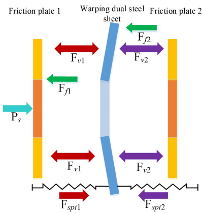
Fig. 3. Axial force diagram of friction plate
2.2.3 Axial Force Analysis
During the engagement process of a wet clutch, assuming that friction plate 1 is fixed in the axial direction, friction plate 2 undergoes axial movement under the influence of the combined pressure Ps in the left-side clearance. Under the combined effects of the oil film bearing force Fv , the micro-protrusion contact force Fa , the spline friction force Ff , and the separation spring elastic force Fspt , the warped dual steel plates experience corresponding axial displacement. The force diagram of the warped dual steel plates in the axial direction is shown in Fig. 3.
Friction plate 1 and the warped dual steel plate form friction pair 1, while friction plate 2 and the warped dual steel plate form friction pair 2. The inter-plate load-bearing forces Fc1 and Fc2 of the two friction pairs are expressed as:
F_{c1} = (1 – \xi_a)\, F_{v1} + F_{a1} ,
\tag{12}
\end{equation}$$
F_{c2} = (1 – \xi_a)\, F_{v2} + F_{a2} ,
\tag{13}
\end{equation}$$
the theoretical contact area of the friction pair; Fv1 and Fv2 are the oil film bearing capacities of friction pair 1 and friction pair 2, respectively [N], Fa1 and Fa2 are the micro-asperity contact forces of friction pair 1 and friction pair 2, respectively [N]. The separation spring elastic forces Fspt1 and Fspt2 on both sides of the warped dual steel plate can be expressed as:
F_{spt1} = k_{spt} \, \Delta h_1 ,
\tag{14}
\end{equation}$$
F_{spt2} = k_{spt} \, \Delta h_2 ,
\tag{15}
\end{equation}$$
where Δh1 is the change in clearance of friction pair 1 [m]; Δh2 is the axial displacement of friction plate 2 [m]; the stiffness of the separation spring kspt is expressed as:
k_{spt} = \frac{N_k E_k b_k \delta_k^3 \cos \alpha_t}{24 R_M^3 k_\beta} ,
\tag{16}
\end{equation}$$
where, Nk is the wave number of the separation spring, Ek is the elastic modulus of the separation spring [Pa], bk is the width of the separation spring [m], δk is the thickness of the separation spring [m], αt is the horizontal angle of the separation spring [°], RM is the radius of the spring [m], kβ is the coefficient associated with the wave number of the separation spring. The friction force kβ at the spline of the friction pair is related to the comprehensive pressure Ps, then the surface specific pressure Psf1 and Psf2 in the gap of friction pair 2 and 1 can be expressed as:
P_{sf2} = P_s – F_{f2}
= P_s \left( 1 + \frac{2 f_a f_2 (r_2^3 – r_1^3)}{3 r_4 (r_2^2 – r_1^2)\cos \alpha_2} \right)^{-1} ,
\tag{17}
\end{equation}$$
\begin{gathered}
P_{sf1} = P_{sf2} – F_{f1} = P_s \left( 1 – \frac{2 f_a f_1 (r_2^3 – r_1^3)}{3 r_3 (r_2^2 – r_1^2)\cos \alpha_1} \right) \\
\quad \cdot \left( 1 + \frac{2 f_a f_1 (r_2^3 – r_1^3)}{3 r_3 (r_2^2 – r_1^2)\cos \alpha_1} \right)^{-1}
\cdot \left( 1 + \frac{2 f_a f_2 (r_2^3 – r_1^3)}{3 r_4 (r_2^2 – r_1^2)\cos \alpha_2} \right)^{-1} ,
\end{gathered}
\tag{18}
\end{equation}$$
where, α1 and α2 are the pressure angles at the spline pairs of the dual steel plate and friction plate, respectively [°], r3 and r4 are the radii of the pitch circle at the spline of the dual steel plate and the friction plate respectively [m], fa, f1 , and f2 are the friction coefficients at the friction pair, dual steel plate spline pair, and friction plate spline pair, respectively. Therefore, the axial force equilibrium equation for the warped dual steel plate can be expressed as:
P_{sf1} = F_{c2} + F_{spt2} + m_s \, a_s ,
\tag{19}
\end{equation}$$
where ms is the mass of the warped dual steel plate [kg], as is the acceleration of the axial displacement of the warped dual steel plate [m/s2]. The axial force equilibrium equation for friction plate 2 is:
P_{sf2} = F_{c2} + F_{spt2} + m_f \, a_f ,
\tag{20}
\end{equation}$$
where mf is the mass of friction plate 2 [kg], af is the acceleration of the axial displacement of friction plate 2 [m/s2].
2.2.4 Analysis of Mechanical Properties of Warped Dual Steel Plate
A simulation solution model for the force-position characteristics of two types of warped dual steel plates was established, using the GB/T 1972.1-2023 disc spring stiffness approximation solution model. The three-dimensional model of the disc-shaped dual steel plate is established, and the finite element simulation is carried out to solve the force-position characteristics of the disc-shaped dual steel plate.
(1) Theoretical model
Approximate solution model of disc spring stiffness:
k_{spr} = \frac{4 E_s}{1 – v_s^2} \cdot \frac{t_s^3}{M D^2}
\left( 1 + \frac{y_0^2}{t_s^2} – \frac{3 y_0 y}{t_s^2} + \frac{3 y^2}{2 t_s^2} \right) ,
\tag{21}
\end{equation}$$
M = \frac{1}{\pi} \cdot
\frac{\left( \frac{C – 1}{C} \right)^2}
{\left( \frac{C + 1}{C – 1} – \frac{2}{\ln C} \right)} ,
\tag{22}
\end{equation}$$
C = \frac{D}{d_1} ,
\tag{23}
\end{equation}$$
where kspr is the stiffness of the disc spring [N/m], ts is the thickness of the disc spring [m], y0 is the maximum compression deformation of the disc spring [m], y is the deformation displacement of the disc spring [m], Es is the elastic modulus of the dual steel plate, vs is the Poisson’s ratio of the dual steel plate, D is the outer diameter of the disc-shaped dual steel plate [m], d1 is the inner diameter of the disc-shaped dual steel plate [m].
(2) Finite element simulation model
The solution model of force-position characteristics of warped dual steel plate is established, and the model is imported into the static structural module of Ansys. The mesh is divided into the mesh function. After the grid independence test, the plate is divided by the sweep method. The mesh unit size is set to 3 mm, and the warped dual steel plate is divided by the tetrahedral method. The mesh unit size is set to 1 mm, and the number of mesh nodes is 372049, the number of mesh units is 212965.
After the mesh is divided, set its boundary conditions and constraints. Set the contact between the dual steel plate and the friction plate as friction contact, with a friction coefficient of 0.1 and asymmetric contact. Apply a fixed constraint to the friction plate on one side of the dual steel plate; apply an axial displacement constraint to the friction plate on the other side, with the displacement direction being the compression direction of the warped dual steel plate. The total displacement is the warped amount. The analysis is set to 5 steps, with each step lasting 1 s.
Using the two aforementioned solution methods, calculations were performed to solve for warped steel plates with warping amounts of 0.2 mm and 0.5 mm, respectively. The force-displacement characteristic curves of the warped steel plates under different warping amounts are shown in Fig. 4.
As can be seen from the analysis of the above figure, during the compression process of the warped steel plate, the compression amount exhibits a linear relationship with the load within the range [0, 0.95]. The stiffness of the warped steel plate under different warping amounts is shown in Table 1. As shown in Table 1, the stiffness results obtained using the theoretical model method and the finite element simulation method have an error of less than 8 %, indicating that the computational model has a certain degree of reliability. Additionally, the stiffness of the warped steel plates at different warping amounts differs only slightly. The stiffness of a disc spring is directly related to the degree of warping, and it exhibits the characteristic of being linearly related to the compression ratio when the compression ratio is small and non-linearly related when the compression ratio is large.
Table 1. Stiffness of warped dual steel plate under different warping amount
| Warpage hq [mm] | 0.2 | 0.5 | |
|---|---|---|---|
| Stiffness, kspr [N·mm−1] | Theoretical model | 2691.25 | 2694.80 |
| Finite element method | 2483.69 | 2505.55 | |
| Relative error [%] | 7.71 | 7.02 |
The compression ratio is within the range of [0.95, 1]. During compression, the lever arm of the warped dual steel plate changes, and its stiffness also changes. During the compression simulation, the maximum internal stress of the warped dual steel plate is 170 MPa, which does not exceed the yield limit, and no plastic deformation occurs during a single engagement process. Therefore, under the current deflection amount and within a limited number of engagement cycles, the force-displacement characteristic curve of the warped dual steel plate remains constant and can be used for simulation modeling and theoretical analysis.
2.3 Circumferential Motion Analysis
During the oil film shear stage, the shear stress factors φf and φfs are introduced into the oil film shear torque model, and the oil film shear torque Tv between the friction pairs can be expressed as:
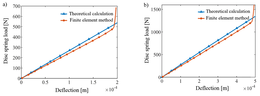
Fig. 4. The force-position characteristic curve of steel plate under warpage of: a) 0.2 mm, and b) 0.5 mm
T_v = \int_0^{2\pi} \int_{R_i}^{R_o}
\left[
\frac{\mu_0 \dot{\gamma}}{\kappa \dot{\gamma}^2 + 1}
\left( \varphi_f + \varphi_{fs} \right)
\right]
r^2 \, dr \, d\theta ,
\tag{24}
\end{equation}$$
where μ0 is the viscosity of the lubricating oil at the inlet [Pas], \( \dot{\gamma} \) is the shear strain rate, expressed as:
\dot{\gamma} = \frac{(\omega_s – \omega_f)\, r}{h} .
\tag{25}
\end{equation}$$
The rough friction torque Ta between friction pairs can be expressed as:
T_a = f_a \frac{A_a}{A_n}
\int_0^{2\pi} \int_{R_i}^{R_o} \frac{F_a}{A_a} r^2 \, dr \, d\theta
= \frac{2}{3} f_a F_a \frac{r_2^3 – r_1^3}{r_2^2 – r_1^2} .
\tag{26}
\end{equation}$$
Through engagement tests conducted on paper-based friction plates and dual steel plates, the relationship between fa and the relative rotational speed of the driving and driven ends can be expressed as:
f_a = 0.13 – 0.01 \ln(\omega_s – \omega_f) .
\tag{27}
\end{equation}$$
Based on the above analysis, during the engagement process of a wet clutch, the gap between the warped friction pairs continuously decreases under the influence of piston oil pressure, and the load end speed increases. When the drive end and load end speeds are the same, they accelerate together to the target speed. The transmitted torque Tf is expressed as:
T_f = \left( (1 – \xi_a)\, T_v + \xi_a \, T_a \right) N .
\tag{28}
\end{equation}$$
The differential equation for the circumferential motion of the friction pair can be expressed as [22,23]:
J \ddot{\theta} = T_f – T_r ,
\tag{29}
\end{equation}$$
where J is the rotational inertia of the driven end [kgm2], and Tr is the resistance torque of the driven end [Nm]. The calculation process for the wet clutch engagement process is shown in Fig. 5.
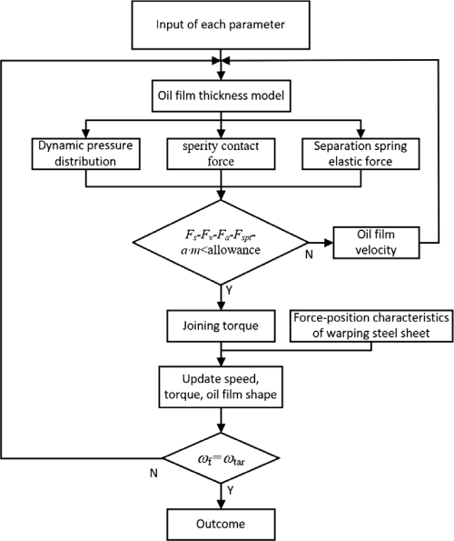
Fig. 5. Calculation flowchart for wet clutch engagement process
3 RESULTS AND DISCUSSION
By coupling the axial motion and circumferential motion, the engagement characteristics of the wet clutch with warped friction pair are obtained. The engagement simulation parameters of the wet friction clutch are shown in Table 2.
Table 2. Engagement simulation parameters
| Category | Parameter | Value |
|---|---|---|
| Operating parameters |
Active end speed ωs | 6000 r/min |
| System moment of inertia J | 0.025 kgm2 | |
| Initial oil film thickness hd | 4×10⁻⁴ m | |
| Piston steady-state loading pressure Ps | 1.2 MPa | |
| Spray parameters |
40 °C viscosity μ40 | 0.012 Pas |
| Density ρ | 870 kg/m3 | |
| Geometric feature |
Friction pair inner radius r1 | 0.059 m |
| Friction pair outer radius r2 | 0.073 m | |
| Clutch piece warping amount hq | 2×10⁻⁴ m | |
| Material properties of friction pair |
Joint roughness root mean square σ | 8.4×10⁻⁶ m |
| Asperity distribution density ρa | 7×10⁷ m−2 | |
| Softer material hardness Ha | 2.8 GPa | |
| Friction plate Poisson ‘s ratio vf | 0.3 | |
| Poisson ‘s ratio of steel plate vs | 0.4 | |
| Elastic modulus of friction plate Es | 10.59 GPa | |
| Elastic modulus of steel plate Ef | 206 GPa | |
| Asperity radius Ra | 8×10⁻⁴ m | |
| Liner material permeability φ | 8×10⁻¹³ m2 |
Table 2 shows the piston pressure loading values, which represent the final steady-state piston pressure during the engagement process. The piston pressure curve is shown in Fig. 6.
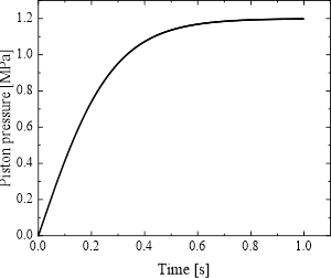
Fig. 6. Piston pressure curve
The function of the piston pressure pressurization method in Fig. 6 is expressed as:
P_{ss} = P_s \tanh(3.6 t) ,
\tag{30}
\end{equation}$$
where Ps is the piston steady-state loading pressure [MPa].
The simulation results are shown in Fig. 7, where Figs. 7a and b show the inter-slice bearing capacity of friction pair 1 and axial force of two friction pairs, respectively; Figs. 7c and d show the engagement torque composition and engagement torque comparison of friction pair 1, respectively; and Figs. 7e, f, and g show the engagement speed, oil film contraction speed, and gap oil film change during the engagement process, respectively. Table 3 shows the key result parameters in the engagement process.
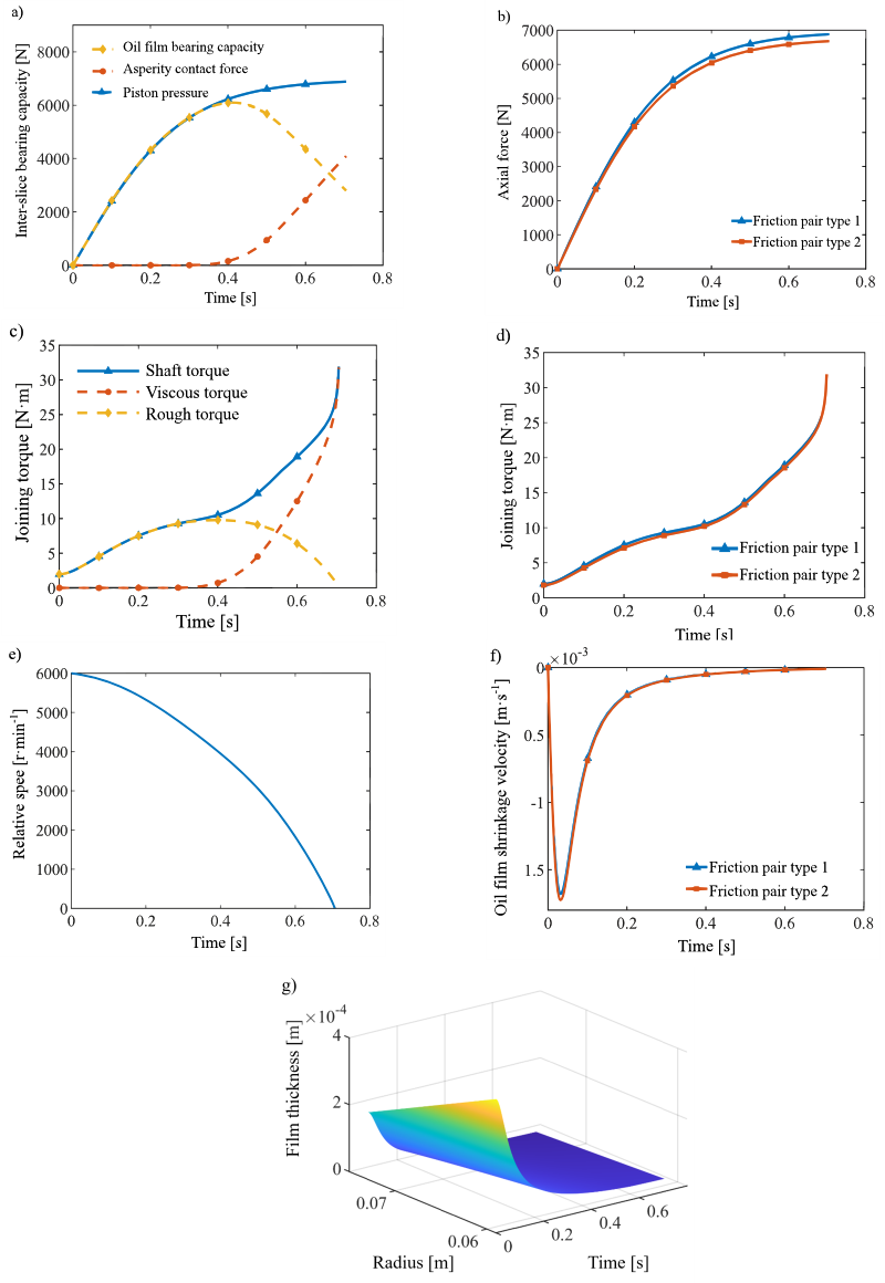
Fig. 7. Simulation results of joint process; a) friction pair type 1 inter-slice bearing capacity, b) axial force of two friction pairs, c) friction pair type 1 engagement torque, d) transfer torque of two friction pairs, e) relative speed, f) oil film shrinkage velocity of two friction pairs, g) interstitial oil film
Table 3. The key result parameters in the friction pair engagement process
| Parameters | Value |
|---|---|
| The duration of the squeeze phase | 0.25 s |
| Duration of the plastic stage of steel plates | 0.56 s |
| Peak oil film bearing capacity | 6000 N |
| Peak asperity contact force | 4000 N |
| Peak viscous torque | 10 Nm |
| Peak rough torque | 32 Nm |
| Peak oil film shrinkage rate | 0.0018 ms−1 |
3.1 Engagement Stage Classification
Existing research typically divides the wet clutch engagement process into three stages: the squeeze phase, the mixed friction phase, and the fully rough friction phase. This classification assumes a perfectly flat friction surface and a uniform clearance. However, this study reveals that the engagement process of a warped friction pair consists of only two stages. In the squeeze phase, the oil film bearing capacity continuously increases, while the micro-asperity contact force remains negligible, and the transmitted torque is entirely governed by viscous shear. In the second stage, the micro-asperity contact force gradually increases with a corresponding decrease in oil film bearing capacity, transitioning the torque transmission from pure viscous torque to a combination of viscous and rough friction torque (Figs. 7a and 7c).
As illustrated in Fig. 7g, oil film thickness varies radially throughout the engagement process, confirming the convergent-divergent clearance characteristics induced by the warped structure. During the late engagement phase, localized regions maintain a residual oil film thickness; consequently, the oil film bearing capacity does not drop to zero (Fig. 7a), and the oil film contraction rate does not completely cease (Fig. 7f). This indicates that the warped structure facilitates persistent oil film retention within the gap, thereby preventing the transition to a fully rough friction stage. This behavior distinctly contrasts with the engagement of flat friction pairs, where, under the assumption of a uniform gap, the oil film is generally considered to be completely expelled. The non-uniform clearance created by the warpage prevents complete localized oil displacement, sustaining a continuous hydrodynamic effect.
During this process, the axial force exerted on the warped dual steel plate exceeds its structural stiffness, causing it to gradually flatten as the oil film contracts. When the compression ratio of the warped steel plate reaches the [0.95, 1] range, a dramatic increase in stiffness prevents further flattening, leaving the clutch plate with a residual warp. Consequently, prior to 0.56 s, which corresponds to 95 % of the maximum deformation, the contact remains in the deformation stage, transitioning to the plastic stage after 0.56 s. This distinct division of steel plate deformation, combined with the residual oil film characteristics, defines the unique engagement process of the warped friction pair: a two-stage lubrication state (squeeze and mixed friction) corresponding to a three-stage structural evolution (non-contact, deformation, and plasticity).
3.2 Load Sharing Characteristics
Existing studies analyzing load sharing in friction pairs have primarily focused on the static distribution ratio between oil film bearing capacity and micro-asperity contact force, with limited discussion on their dynamic evolution during the engagement process and its correlation with geometric non-uniformity. This research has observed several noteworthy dynamic characteristics.
During the initial squeeze stage, piston pressure is predominantly balanced by the hydrodynamic pressure of the oil film. When the piston pressure reaches approximately 0.09 MPa (corresponding to t = 0.02 s in Fig. 6), a significant oil film contraction rate is observed (Fig. 7f). This phenomenon results from the negative feedback regulation of the squeeze process by the increasing hydrodynamic pressure: initially, a thicker oil film allows the squeeze effect to dominate. However, as the clearance decreases, the dynamic pressure bearing capacity rises, which subsequently inhibits further contraction of the oil film. This dynamic response is difficult to capture in traditional analyses based on steady-state or quasi-static assumptions, and its actual impact warrants further investigation. Upon entering the mixed friction stage, both the hydrodynamic pressure of the oil film and the asperity contact force act as the primary load bearers. Compared to uniform clearance conditions, the presence of the warped structure fundamentally alters the oil film pressure distribution.
3.3 Torque Transmission Difference
Regarding torque distribution in multi-friction-pair systems, existing research often assumes uniform force distribution across friction pairs or primarily focuses on overall torque without analyzing differences between pairs. In this study, torque transmission varies between the two friction pairs (Fig. 7d), with torque slightly lower in friction pair 2.
Analysis of force transmission path: After the piston pressure first acts on friction pair 1, it must be transmitted to friction pair 2 via the warped counterpart steel plate. Concurrently, factors such as spline friction resistance influence the process, resulting in pressure attenuation during transmission. This causes the actual pressure within the clearance of friction pair 2 to be lower than that of friction pair 1 (Fig. 7b). This pressure differential affects oil film thickness and micro-asperity contact conditions, consequently leading to torque variation.
As the warped steel plates are gradually flattened, the torque difference is also reduced. This indicates that geometric non-uniformity is a significant factor contributing to uneven pressure distribution. Once warping deformation is eliminated, pressure distribution tends toward uniformity, and torque transmission consistency improves accordingly. In multi-friction-pair systems, the extent of this geometric-mechanical coupling effect may be influenced by factors such as the number of friction pairs and warpage distribution, warranting further investigation.
3.4 Clutch Engagement Characteristic Test
In this chapter, the wet clutch friction pair of the warped friction pair was tested by using the MM6000 friction tester to verify the accuracy of the simulation results. In the supplementary information section, the test equipment, test system composition and test pieces are described in detail. Fig. 8 shows a comparison between the simulation results and experimental results for the engagement torque of warped friction pair type 1 and friction pair type 2.
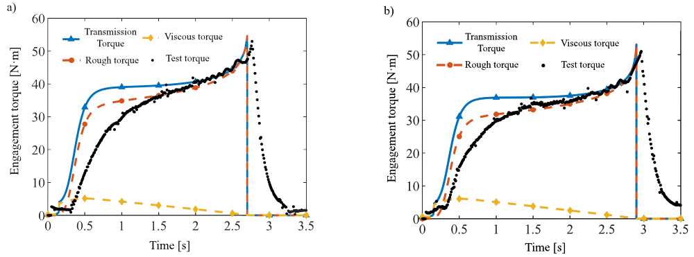
Fig. 8. Torque test results and simulation comparison of friction pair type of: a) 1, and b) 2
Table 4 shows a comparison between the average engagement time of multiple engagement tests and the simulation results.
As shown in Fig. 8, for friction pair types 1 and 2, the simulation results of the engagement torque are consistent with the experimental results in terms of trend and peak engagement torque [24]. The relative error between the tested and simulated engagement time is small, but there are certain differences in the transmitted torque during the initial and final stages of engagement. During the initial engagement phase, the experimental torque is lower, and its rate of change is smaller compared to the simulated torque. This occurs because the active-end fixture and the warped dual steel plate utilize a clearance fit. Under axial loading, the warped face of the steel plate acts as the axial positioning structure. This causes the plate to tilt, which transitions the rough contact between the friction pairs from full to partial contact, thereby temporarily reducing the transmitted torque. At the conclusion of the engagement process, the driven end continues to experience residual torque transmission even after macroscopic engagement is complete. This is attributed to a mechanical lag; after the drive-end clamping device partially completes braking, the drive-end transmission components lag in achieving full synchronous engagement, thereby exerting continued torque on the friction pair. Despite these minor transient deviations, the established dynamic model for warped friction pairs accurately predicts critical parameters such as engagement torque and time, providing a robust theoretical foundation for diagnosing warped clutch plate faults in wet clutches.
Table 4. Comparison of engagement time between test and simulation
| Friction pair type 1 | Friction pair type 2 | |
|---|---|---|
| Test result [s] | 2.93 | 3.12 |
| Simulation result [s] | 2.70 | 2.90 |
| Error [%] | 8.5 | 7.6 |
4 CONCLUSIONS
This study constructed a coupling model that considers the average Reynolds equation, K-E contact model, and coupling warping characteristics, combined with equation derivation, axial and circumferential motion coupling analysis, and simulation and experimental verification, and obtained the following conclusions:
1. Warped dual steel plates exhibit linear stiffness at compression ratios below 0.95. Beyond this threshold, stiffness increases nonlinearly due to changes in the lever arm during compression.
2. Analysis of the torque and force-displacement characteristics reveals that, unlike traditional planar friction pairs, the engagement of a warped friction pair consists exclusively of a squeeze phase and a mixed friction phase. Due to the persistent retention of the oil film within the non-uniform clearance, a completely rough friction stage does not occur. Concurrently, the deforming steel plate transitions through three distinct structural phases: non-contact, deformation, and plastic deformation.
3. The load sharing between the oil film and the micro-asperities demonstrates a dynamic evolutionary pattern. During the initial squeeze phase, the piston pressure is primarily balanced by the oil film’s hydrodynamic pressure. At the onset of pressure application, the oil film contracts rapidly but is soon stabilized by a negative feedback mechanism driven by the rising dynamic pressure. During the mixed friction phase, the load is jointly supported by both the hydrodynamic pressure and the micro-asperity contact forces.
4. A noticeable difference in torque transmission exists between the two friction pairs, with friction pair 2 transmitting slightly lower torque due to pressure attenuation caused by spline friction. As engagement progresses and the warped steel plates gradually flatten, the geometric discrepancies between the pairs decrease, consequently narrowing the torque disparity. This underscores geometric non-uniformity as a critical factor driving uneven pressure distribution in multi-disc friction systems.
Nomenclatures
χ Beaver-Joseph factor,
α sliding coefficient,
d thickness of the friction lining, [m]
ϕ0 permeability of the friction lining material, [m–2]
φr radial,
φθ circumferential pressure flow factor,
φs shear flow factor,h oil film thickness, [m]
ρ lubricant density, [kg/m3]
ωs rotational speeds of the mating steel plate, [rad/s]
ωf rotational speeds of the friction plate, [rad/s]
μ lubricant viscosity, [Pas]
σ root mean square of the combined surface roughness, [m]
Ps stable piston pressure value, [Pa]
ωtar target clutch engagement speed, [rad/s]
μ40 viscosity of the lubricating oil at 40 °C, [Pas]
r1 internal radius of friction pair, [m]
r2 outer radius of friction pair, [m]
hd average oil film thickness, [m]
Ra radius of the micro-asperity, [m]
K hardness correlation coefficient,
ρa density of the micro-asperity, [m–2]
ha distance between the average height of the micro-asperity on the equivalent rough surface and the rigid plane, [m]
δc critical deformation, [m]z height of the micro-asperity, [m]
σz roughness of the surface of the dual steel plate,
Aa contact area between friction pairs, [m2]
Fa micro-protrusion bearing capacity, [N]
An nominal contact area, [m2]
Ha hardness of the equivalent rough surface material, [Pa]
Fc1 inter-slice bearing capacity of friction pair 1, [N]
Fc2 inter-slice bearing capacity of friction pair 2, [N]
ξa ratio of the actual contact area to the theoretical contact area of the friction pair,
Fv1 oil film bearing capacity of friction pair 1, [N]
Fv2 oil film bearing capacity of friction pair 2, [N]
Fa1 asperity contact force of friction pair 1, [N]
Fa2 asperity contact force of friction pair 2, [N]
Fspt1 separation spring elastic force of friction pair 1, [N]
Fspt2 separation spring elastic force of friction pair 2, [N]
Δh1 change in clearance of friction pair 1, [m]
Δh2 change in clearance of friction pair 2, [m]
kspt stiffness of the separation spring,
Nk wave number of the separation spring,
Ek elastic modulus of the separation spring, [Pa]
δk thickness of the separation spring, [m]
bk width of the separation spring, [m]
αt horizontal angle of the separation spring, [°]
RM radius of the spring, [m]
kβ coefficient associated with the wave number of the separation spring,
Psf1 surface specific pressure in the gap of friction pair 1,
Psf2 surface specific pressure in the gap of friction pair 2,
α1 pressure angle at the spline of the dual steel plate, [°]
α2 pressure angle at the spline of the friction plate, [°]
r3 pitch circle radius of the spline of the dual steel plate, [m]
r4 pitch circle radius of the spline of the friction plate, [m]
fa friction coefficients at the friction pair,
f1 friction coefficients at the mating steel plate spline pair,
f2 friction coefficients at the friction plate spline pair,
ms mass of the warped dual steel plate, [kg]
as acceleration of the axial displacement of the warped dual steel plate, [m/s2]
mf mass of friction plate 2, [kg]
af acceleration of the axial displacement of friction plate 2, [m/s2]
kspr stiffness of the disc spring, [N/m]
Pspr load of a single disc spring, [N]
ts thickness of the disc spring, [m]
y0 maximum compression deformation of the disc spring [m]
y deformation displacement of the disc spring, [m]
Es elastic modulus of the dual steel plate, [Pa]
D outer diameter of the disc-shaped dual steel plate, [m]
d1 inner diameter of the disc-shaped dual steel plate, [m]
vs Poisson’s ratio of the dual steel plate,
Tv oil film shear torque between friction pairs, [Nm]
Ta rough friction torque between friction pairs, [Nm]
fa coefficient of friction,
Tf shaft torque, [Nm]
J rotational inertia of the driven end [kgm2]
Tr resistance torque of the driven end. [Nm]
References
[1] Davim, P. (ed.) Tribology for Engineers: A Practical Guide. Woodhead Publishing (Elsevier) Cambridge (2011), DOI:10.1533/9780857091444.
[2] Davim, P. Additive manufacturing: A bibliometric analysis. Int J Mater Eng Innov16 2-3 (2025).
[3] Patir, N., Cheng, H.S. An average flow model for determining effects of three-dimensional roughness on partial hydrodynamic lubrication. J Tribol 100 12-17 (1978) DOI:10.1115/1.3453103.
[4] Beavers, G.S., Joseph, D.D. Boundary conditions at a naturally permeable wall. J Fluid Mech 30 197-207 (1967) DOI:10.1017/S0022112067001375.
[5] Berger, E.J., Sadeghi, F., Krousgrill, C.M. Finite element modeling of engagement of rough and grooved wet J Tribol 118 137-146 (1996) DOI:10.1115/1.2837069.
[6] Jang, Y., Khonsari, M.M. Thermal characteristics of a wet clutch. J Tribol 121 610-617 (1999) DOI:10.1115/1.2834111.
[7] Jang, J.Y., Khonsari, M.M., Maki, R. Three-dimensional thermohydrodynamic analysis of a wet clutch with consideration of grooved friction surfaces. J Tribol 133 011703 (2011) DOI:10.1115/1.4003019.
[8] Zhang, Z., Zou, L., Liu, H., Feng, J., Chen, Z. Response characteristics of dynamic torque for wet clutch engagement: A numerical and experimental Shock Vib (2021) DOI:10.1155/2021/5522998.
[9] Huang, W., Bao, H.Y., Zhu, C., Zhu, R.P. Analysis of squeeze process and engagement characteristics of wet friction J Aerosp Power 37 1992-2000 (2022) DOI:10.13224/j.cnki.jasp.20210353. (in Chinese )
[10] Jin, J., Li, X., Yang, S., Yi, H., Sun, H., Hao, W. Calculation and analysis of wet clutch sliding torque based on fluid-solid coupling dynamic behavior. Tribology Int 202 110363 (2025) DOI:10.1016/j.triboint.2024.110363.
[11] Greenwood, A., Williamson, J.B.P. Contact of nominally flat surfaces. Proc R Soc A Math Phys Eng Sci 295 300-319 (1966) DOI:10.1098/rspa.1966.0242.
[12] Majumdar, A., Bhushan, B. Fractal model of elastic-plastic contact between rough surfaces. J Tribol 113 1-11 (1991) DOI:10.1115/1.2920588.
[13] Kogut, L., Etsion, I. Elastic-plastic contact analysis of a sphere and a rigid flat. J Appl Mech 69 657-662 (2002) DOI:10.1115/1.1490373.
[14] Masjedi, M., Khonsari, M.M. On the effect of surface roughness in point-contact EHL: Formulas for film thickness and asperity Tribol Int 82 228-244 (2015) DOI:10.1016/j.triboint.2014.09.010.
[15] Wang, Y.Z., Li, Y., Liu, Y., Zhang, W. Modeling and experimental research on engaging characteristics of wet Ind Lubr Tribol 71 94-101 (2019) DOI:10.1108/ILT-12-2017-0383.
[16] Wu, P., Cui, J.H., Shu, W.Y., Wang, L.Y., Chen, R.H. Elastohydrodynamic lubrication model and failure test for micro-contact thermodynamic characteristics of friction interface. Tribol Int 185 108499 (2023) DOI:10.1016/j.triboint.2023.108499.
[17] Yang, C.L., Wu, P.H., Shang, X.B., Wang, Z.S. Simulation and experimental study of engagement process with groove consideration. J Zhejiang Univ (Eng Sci) 53 1225-1236 (2019) DOI:10.3785/j.issn.1008-973X.2019.07.001. (in Chinese)
[18] Bao, H.Y., Huang, W., Lu, F.X. Investigation of engagement characteristics of a multi-disc wet friction clutch. Tribol Int 159 106940 (2021) DOI:10.1016/j. 2021.106940.
[19] Bao, Y., Xu, T.J., Jin, G.H., Huang, W. Analysis of dynamic engaged characteristics of wet clutch in variable speed transmission of a helicopter. Processes 8 1474 (2020) DOI:10.3390/pr8111474.
[20] Ozdemir, E.T., Inalpolat, M., Lee, H.K., Kim, M.S. A generalized multibody dynamic model for dual-clutch transmissions with wet clutchsets. Proc Inst Mech Eng Part K: J Multi-body Dyn 239 (2025) DOI:10.1177/14644193251346325.
[21] Wu, P., Cui, J.H., Shu, W.Y., Wang, L.Y., Li, H.Y. Coupling mechanism and data-driven approaches for high power wet clutch torque modeling and analysis. Tribol Int 191 109166 (2024) DOI:10.1016/j.triboint.2023.109166.
[22] Minas, I., Morris, N., Theodossiades, S., O’Mahony, M., Voveris, J. Automotive dry clutch fully coupled transient tribodynamics. Nonlin Dyn 105 1213-1235 (2021) DOI:10.1007/s11071-021-06605-x.
[23] Zhu, C., Chen, Z., Shi, Z.C., Zhang, Y.D. Study on the engagement characteristics and control strategy of high speed difference dry friction Machines 11 407 (2023) DOI10.3390/machines11030407.
[24] Song, Z., Chen, Y., Chen, Z., Yang, X., Jiang, Z., Zhou, Y., et al. Study on the dynamic and thermal field characteristics of the engagement process of high power density and high speed difference dry friction clutch. Appl Therm Eng 288 129547 (2026) DOI:10.1016/j.applthermaleng.2025.129547.