

1 INTRODUCTION
The crankshaft-bearing system is the core structure of an engine. It is the structure of the output power, and the part that periodically bears severe and complex loads. As a key rotating assembly in internal combustion engines, the crankshaft-bearing system is responsible for torque transmission and bears multi-directional dynamic loads generated by gas pressure, inertia forces, and bending-torsional vibration. Its stiffness distribution and deformation behavior significantly influence the stability, lubrication and service life of the main bearings. Therefore, achieving coordinated deformation between the crankshaft and its supporting structure is essential for improving the reliability and overall performance of engines.
A vehicle is an extremely complex technical system composed of many interconnected subsystems, with many key components relying on the interaction of load-carrying surfaces during operation. In particular, engine and drivetrain components such as piston rings, main bearings, valve guides, tappet shims, fuel-injector plungers, transmission gears, and face seals are significantly influenced by friction and wear. Designing such friction pairs requires selecting appropriate structural configurations, materials of high wear resistance and low friction, and suitable lubrication strategies. These characteristics have been emphasized in recent tribological studies and have prompted the need to understand the structural-tribological coupling in crankshaft-bearing systems [1-2].
Cho and Jung [3] theoretically analyzed the friction characteristics between crankshaft and bearing. The results showed that friction characteristics were affected by the clearance between crankshaft and plain bearing and the oil viscosity. Rong [4] introduced a calculation method for large deformation of multi-flexible body systems, and verified the effectiveness of this method using a crank connecting rod mechanism. Choi et al. [5] analyzed the lubrication characteristics of bearings using a multi-body model with elastohydrodynamic lubrication, and solved the system problem of fluid structure coupling. Bai et al. [6] compared the crankshaft strength through continuous beam method and simulation based finite element analysis (FEA). Other studies mainly focus on the stress-strain analysis of a single component under a single load, especially the cylinder head and cylinder liner [7-11]. For example, Zhai et al. [12] used a flexible body model to model piston cylinder liner friction pairs, providing more accurate boundary conditions for tribological calculation. Bi et al. [13] established a fluid-structure coupling model for cylinder head, cylinder liner, cooling water and body. They studied the influence of coolant flow uniformity on the hot deformation of cylinder liner, and optimized the flow characteristics of water distribution holes of the body and water holes on the cylinder head. The structure of the diesel engine block has also been optimized, and significant progress has been made in the dynamics and tribology of the crankshaft bearing system [14-15]. However, they mainly focus on crankshaft stiffness or bearing lubrication, ignoring the interaction between the two components. Zhang et al. [16] established a dynamic tribological coupling model of the crankshaft-bearing system for coupling analysis. The results showed that the influence of crankshaft and body deformation on the lubrication performance of the main bearing should not be ignored. Yu et al. [17] studied the coupling characteristics of crankshaft transient vibration and bearing lubrication, and improved the coupling calculation method of the dynamics and lubrication of the crankshaft-bearing system. Considering the influence of temperature on friction lubrication, Wei et al. [18] established a thermo elasto hydro dynamic (TEHD) mixed lubrication model for the coupling of main bearing with crankshaft of marine diesel engine body. Shao et al. [19] established an elastic hydrodynamic lubrication model for crankshaft main bearings (including thermal effects), based on the influencing factors of lubrication. The analysis results show that thermal effect included has a great influence on crankshaft main bearing. Gao et al. [20] discussed the analysis model, calculation methods and influencing factors of the dynamics, tribology and coupling of crankshaft-bearing system of internal combustion engine. Based on the mean Reynolds equation and the dynamic adaptation equation considering bump contact, Wang et al. [21] established a TEHD calculation model for crankshaft main bearing of internal combustion engine. They analyzed its lubrication and friction characteristics, discussed the mechanism of heat production and heat transfer, and obtained the effect rules. Based on particle swarm optimization (PSO), Tong et al. [22] carried out a multi-objective optimization in the design of the main shaft bearing system. This design optimization considers several objectives such as natural frequency, static stiffness and total frictional torque, and the target was significantly improved. Zhan et al. [23] established a boundary element model discretized by discontinuous iso-parametric quadratic boundary elements and compared it with the experimental data and finite element method (FEM). This model is more suitable for thermal deformation coupling calculation and has high universality and accuracy.
Tribological studies have revealed several influential factors that cannot be fully incorporated into this model, including the contact behavior of rough surfaces, influence of lubricant formulation, thermo-dynamic balance of mass, energy and entropy in lubrication films, and self-organization mechanisms in the friction system. Although these factors are crucial for understanding detailed lubrication behaviors, this study focuses on deformation coordination at the system level.
For the design of high-intensity diesel engine, it is necessary to consider the deformation of crankshaft and its supporting structure during movement and the deformation coordination between them.
When the crankshaft deforms under complex loads, a single main bearing often shows inconsistent support displacements, resulting in misalignment, uneven distribution of oil-film pressure, and a decrease in the minimum film thickness. Therefore, improving the consistency (coordination) of these support displacements is crucial for preventing edge loading, localized wear and premature bearing failure.
Most studies focus on crankshaft stiffness or bearing tribology independently, and only a few consider their coupling behaviors. The crankshaft deformation will change the attitude angle of each journal, which in turn influences oil-film thickness and bearing reaction forces, forming a closed-loop structure-lubrication interaction. Neglecting this coupling may lead to inaccurate evaluation of bearing loads and stiffness-matching performance.
To overcome these limitations, we develop an analytical continuous-beam model for the crankshaft-bearing system to derive a deformation-coordination equation connecting bearing reactions and support displacements. This model integrates a simplified hydrodynamic lubrication model to describe oil-film-controlled bearing compliance. In addition, a tolerance based structural optimization framework is proposed with relative bearing clearance as the optimization variable and displacement variance as the objective function.
This framework was further assessed under dynamic crankshaft loading and compared with finite-element predictions. The results show that this method can capture the deformation-coordination behavior of the crankshaft-bearing system with high accuracy while maintaining high computational efficiency. This makes the method suitable for tolerance design and rapid evaluation of bearing-clearance schemes, particularly under severe operating conditions.
2 METHODS & MATERIALS
2.1 Crankshaft Shafting Deformation Coordination
The calculation model shown in Fig. 1 can be obtained by treating the crankshaft system as a continuous beam placed on each rigid hinge support. To analyze the interaction between the crankshaft and its multiple bearing supports, the crankshaft is idealized as a continuous Euler-Bernoulli beam resting on seven supports. The Euler-Bernoulli beam formulation neglects torsional deformation. This simplification is justified to analyze the bearing support reactions under quasi-static peak loading, where bending-induced misalignment dominates oil-film load redistribution. Torsional effects become significant for vibration, fatigue, and dynamic response analysis, which goes beyond the scope of the deformation-coordination framework. This formulation can derive the coordination conditions between support reactions and deflection in a closed form. This is crucial for evaluating the deformation coordination of the shafting under complex loads.
This rigid-support assumption is due to the fact that the crankcase structure of heavy-duty engines typically shows a bending stiffness one to two orders of magnitude higher than that of the crankshaft. Although bearing housings are not completely rigid, finite-element studies have demonstrated that their deformation contributes less than 3 % to 5 % to the overall support displacement. Therefore, the continuous-beam approximation captures the dominant characteristics of crankshaft deformation and load redistribution, thereby enabling efficient analysis modeling. For clarity and conciseness, the Supplementary Information (SI) provides a detailed derivation of the beam compatibility equation. Only the control equations required for system level analysis are retained in the main text.
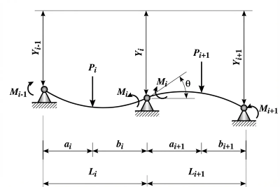
Fig. 1. The release body of the left and right span beams at the ith support
At support i, the rotation angle θ is obtained through deformation superposition and induced by the bending moments Mi–1 and Mi, the concentrated load Pi, and the uniformly distributed load qi . Li is the span length; Ei and Ii represent the elastic modulus and the second moment of area of the shaft segment; ai indicates the distance from the concentrated load to the support, and Yi denotes the vertical displacement of the i th support. i–1 and i+1 refer to adjacent spans. The coordination equation of crankshaft deformation can be obtained as follows:
\begin{gathered}
\frac{M_{i-1}}{6E_i I_i}L_i
+ \frac{M_i}{3E_i I_i}L_i
+ \frac{M_i}{3E_{i+1} I_{i+1}}L_{i+1}
+ \frac{M_{i+1}}{6E_{i+1} I_{i+1}}L_{i+1}
+ \frac{q_i L_i^3}{24E_i I_i}
+ \frac{Y_i – Y_{i-1}}{L_i} \\
= – \frac{P_i a_i (L_i^2 – a_i^2)}{6E_i I_i L_i}
– \frac{P_{i+1} a_{i+1}(L_{i+1}^2 – a_{i+1}^2)}{6E_{i+1} I_{i+1} L_{i+1}}
– \frac{q_{i+1}L_{i+1}^3}{24E_{i+1} I_{i+1}}
– \frac{Y_i – Y_{i+1}}{L_{i+1}}
\end{gathered}
\tag{1}
\end{equation}$$
Sort it out:
\begin{gathered}
\frac{L_i}{E_i I_i}M_{i-1}
+ 2\left(
\frac{L_i}{E_i I_i}
+ \frac{L_{i+1}}{E_{i+1} I_{i+1}}
\right)M_i
+ \frac{L_{i+1}}{E_{i+1} I_{i+1}}M_{i+1} \\
= – \frac{P_i a_i (L_i^2 – a_i^2)}{E_i I_i L_i}
– \frac{P_{i+1} a_{i+1}(L_{i+1}^2 – a_{i+1}^2)}{E_{i+1} I_{i+1} L_{i+1}}
– \frac{q_i L_i^3}{4E_i I_i} \\
\quad
– \frac{q_{i+1}L_{i+1}^3}{4E_{i+1} I_{i+1}}
+ 6\frac{Y_{i-1}}{L_i}
– 6\left(
\frac{1}{L_i} + \frac{1}{L_{i+1}}
\right)Y_i
+ 6\frac{Y_{i+1}}{L_{i+1}}
\end{gathered}
\tag{2}
\end{equation}
$$
Eqs. (1) and (2) are expressed as a matrix:
A \cdot M = B + C = B + 6DY
\tag{3}
\end{equation}
$$
M = A^{-1}(B + C)
= A^{-1}B + 6A^{-1}C
= A^{-1}B + 6A^{-1}DY
\tag{4}
\end{equation}
$$
where:
A =
\left(
\begin{array}{ccccc}
\dfrac{L_1}{E_1 I_1} & & & & \\
\dfrac{L_2}{E_2 I_2}
& 2\left(
\dfrac{L_2}{E_2 I_2}
+ \dfrac{L_3}{E_3 I_3}
\right)
& \dfrac{L_3}{E_3 I_3}
& & \\
& & \ddots & & \\
& &
\dfrac{L_{n-1}}{E_{n-1} I_{n-1}}
& 2\left(
\dfrac{L_{n-1}}{E_{n-1} I_{n-1}}
+ \dfrac{L_n}{E_n I_n}
\right)
& \dfrac{L_n}{E_n I_n} \\
& & & &
\dfrac{L_{n+1}}{E_{n+1} I_{n+1}}
\end{array}
\right)
\end{equation}
$$
B =
\left(
\begin{array}{c}
-\dfrac{q_1 L_1^3}{2E_1 I_1} \\
-\dfrac{q_1 L_1^3}{4E_1 I_1}
-\dfrac{q_3 L_3^3}{4E_3 I_3} \\
\vdots \\
-\dfrac{q_{n-1}L_{n-1}^3}{4E_{n-1} I_{n-1}}
-\dfrac{q_n L_n^3}{4E_n I_n} \\
-\dfrac{q_{n+1}L_{n+1}^3}{4E_{n+1} I_{n+1}}
\end{array}
\right)
+
\left(
\begin{array}{c}
-\dfrac{P_1 L_1^2}{2E_1 I_1} \\
-\dfrac{P_2 a_2 (L_2^2-a_2^2) q_1 L_1^3}{6E_2 I_2 L_2}
-\dfrac{P_3 a_3 (L_3^2-a_3^2)}{6E_3 I_3 L_3} \\
\vdots \\
-\dfrac{P_n a_n (L_n^2-a_n^2)}{6E_n I_n L_n}
-\dfrac{P_{n+1}a_{n+1}(L_{n+1}^2-a_{n+1}^2)}{6E_{n+1} I_{n+1} L_{n+1}} \\
-\dfrac{P_{n+1}L_{n+1}^2}{2E_{n+1} I_{n+1}}
\end{array}
\right)
\end{equation}
$$
\begin{aligned}
C &=
\left(
\begin{array}{c}
0 \\
6\dfrac{Y_1}{L_2}
– 6\left(
\dfrac{1}{L_2}+\dfrac{1}{L_3}
\right)Y_2
+ 6\dfrac{Y_3}{L_3} \\
\vdots \\
6\dfrac{Y_{i-1}}{L_i}
– 6\left(
\dfrac{1}{L_i}+\dfrac{1}{L_{i+1}}
\right)Y_i
+ 6\dfrac{Y_{i+1}}{L_{i+1}} \\
0
\end{array}
\right)
= 6DY =\\
&=
6
\left(
\begin{array}{ccccc}
0 & 0 & & & \\
\dfrac{1}{L_2}
& -\left(
\dfrac{1}{L_2}+\dfrac{1}{L_3}
\right)
& \dfrac{1}{L_3}
& & \\
& & \ddots & & \\
& &
\dfrac{1}{L_{i-1}}
& -\left(
\dfrac{1}{L_{i-1}}+\dfrac{1}{L_i}
\right)
& \dfrac{1}{L_i} \\
& & & 0 & 0
\end{array}
\right)
\times
\left(
\begin{array}{c}
Y_1 \\
Y_2 \\
\vdots \\
Y_{i-1} \\
Y_i
\end{array}
\right)
\end{aligned}
\end{equation}$$
M =
\left(
\begin{array}{c}
M_1 \\
\vdots \\
M_i
\end{array}
\right)
\end{equation}$$
2.2 Support Reaction Calculation
Let the support reaction force at the ith support be Ri, it can be divided into two parts Ri‘ and Ri”. Ri‘ keeps the shaft segment Li balanced,
R_i^\prime
=
\frac{M_{i-1}-M_i}{L_i}
+
\frac{P_i a_i}{L_i}
+
\frac{q_i L_i}{2}
\tag{5}
\end{equation}
$$
Another part Ri” keeps the Li+1 shaft segment balanced. According to the moment balanced:
R_i^{\prime\prime}
=
\frac{M_{i+1}-M_i}{L_{i+1}}
+
\frac{P_{i+1} b_{i+1}}{L_{i+1}}
+
\frac{q_{i+1}L_{i+1}}{2}
\tag{6}
\end{equation}
$$
The reaction force at the ith bearing can be obtained as follows:
\begin{gathered}
R_i = R_i^\prime + R_i^{\prime\prime} \\
=
\frac{M_{i-1}-M_i}{L_i}
+
\frac{M_{i+1}-M_i}{L_{i+1}}
+
\frac{P_i a_i}{L_i}
+
\frac{P_{i+1}b_{i+1}}{L_{i+1}}
+
\frac{q_i L_i}{2}
+
\frac{q_{i+1}L_{i+1}}{2}
\end{gathered}
\tag{7}
\end{equation}
$$
Equations (6) and (7) are represented by a matrix:
\begin{gathered}
R = D^\prime M + F
=
(D^\prime A^{-1}B + F)
+
6D^\prime A^{-1}DY \\
=
R_0 + \Delta R
=
R_0 + EY
\end{gathered}
\tag{8}
\end{equation}
$$
where:
D^\prime =
\left(
\begin{array}{ccccc}
0 & 0 & & & \\
\dfrac{1}{L_2}
& -\left(
\dfrac{1}{L_2}+\dfrac{1}{L_3}
\right)
& \dfrac{1}{L_3}
& & \\
& & \ddots & & \\
& &
\dfrac{1}{L_{i-1}}
& -\left(
\dfrac{1}{L_{i-1}}+\dfrac{1}{L_i}
\right)
& \dfrac{1}{L_i} \\
& & & 0 & 0
\end{array}
\right)
\end{equation}
$$
F =
\left(
\begin{array}{c}
\dfrac{q_1 L_1}{2} + \dfrac{q_2 L_2}{2} \\
\dfrac{q_2 L_2}{2} + \dfrac{q_3 L_3}{2} \\
\vdots \\
\dfrac{q_{n-1}L_{n-1}}{2} + \dfrac{q_n L_n}{2} \\
\dfrac{q_n L_n}{2} + \dfrac{q_{n+1}L_{n+1}}{2}
\end{array}
\right)
+
\left(
\begin{array}{c}
\dfrac{P_1 a_1}{L_1} + \dfrac{P_2 b_2}{L_2} \\
\dfrac{P_2 a_2}{L_2} + \dfrac{P_3 b_3}{L_3} \\
\vdots \\
\dfrac{P_{n-1}a_{n-1}}{L_{n-1}} + \dfrac{P_n b_n}{L_n} \\
\dfrac{P_n a_n}{L_n} + \dfrac{P_{n+1}b_{n+1}}{L_{n+1}}
\end{array}
\right)
\end{equation}
$$
Equations (12) to (14) shows the local equilibrium of each crankshaft span and yield a system of linear equations of the support reactions. These counteracting forces represent the fluid dynamic loads that each bearing experiences during the worst crank angle, forming the basis of the lubrication analysis described in Section 2.4.
It can be seen from Eqs. (9) and (14) that the bearing support reaction force is jointly affected by the geometric parameters of the crankshaft system, external load and support displacement distance. The displacement distance of the bearing depends on the shape and position of the oil film, bearing deformation and installation error, and numerical determination is difficult. In the calculation results, the order of magnitude ∆R of the bearing displacement distance on the support reaction is only 10-3 N. The impact of the error caused by this factor on the calculation results of the supporting reaction force can be ignored. Therefore, Eq. (15) is simplified as follows:
R = D^\prime M + F = D^\prime A^{-1}B + F
\tag{9}
\end{equation}
$$
2.3 FEA of Crankshaft
To verify the analysis formula and assess the accuracy of the continuous-beam model, a three-dimensional FEM of the crankshaft-bearing system is constructed. The FEM captures the true geometry of the crankshaft, including the main journals, crank throws, fillets, and counterweights, providing a high-fidelity reference solution. To ensure the accuracy of the FEA results, the geometric model of the structure should be established as far as possible according to the real object. However, the crankshaft support structure studied is an integral structure including the whole body, and it is difficult to establish its FEM based on real objects. In accordance with established FE modeling practices for crankshaft, the engine block is simplified by only maintaining the main bearing saddles and omitting the bulk block structure.
This simplification is further supported by published studies on theelastic interaction between the crankshaft and the engine crankcase [24,28]. The stiffness characteristics of the crankshaft-crankcase assembly have a significant influence on the distribution of the main bearing load. The crankcase has significantly higher structural stiffness than the crankshaft in typical engine architectures. The results indicate that crankshaft bending deformation plays a key role in the redistribution of bearing load, and the contribution of crankcase deformation is comparatively limited. Therefore, in the finite element analysis of crankshaft bearing systems, a simplified block representation method that only retains the bearing housing is usually used, without affecting the accuracy of bearing load prediction [2,24]. The simplified model and bearings 1-7 are shown in Fig. 2.
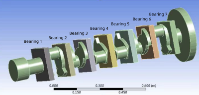
Fig. 2. Simplified model of crankshaft geometry
As shown in Fig. 3, the integral crankshaft FEM is divided into hexahedral elements, consisting of 36012 nodes and 21379 elements. The Supplementary Information (SI) provides a detailed mesh convergence study, confirming that mesh refinement leads to a deviation of less than 3.4 % in bearing reaction forces.
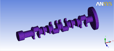
Fig. 3 FEM of crankshaft
Boundary condition procedure
The engine is driven by the pressure of the cylinder pistons. The cylinder pressure curve is adjusted according to the engine firing sequence left 1→ right 6→ left 5→ right 2→ left 3→ right 4→ left 6→ right 1→ left 2→ right 5→ left 4→ right 3. The 90-degree phase difference from left cylinder to right cylinder and 30-degree difference from right cylinder to left cylinder to obtain the crankshaft load at any corner position within a working cycle of the crankshaft, as shown in Fig. 4.
The cylinder pressure curves used to establish the gas-force history in Fig. 4 correspond to the rated full-load operating condition of the target diesel engine. The pressure trajectory in each cylinder is obtained from an internal performance simulation model calibrated based on test data of similar engines. Then, based on the instantaneous cylinder pressure, piston area and geometric shape of the crank-slider mechanism, the gas force acting on each crank pin is calculated, and this force is converted into an equivalent load acting on the crank stroke. By superposing the contributions of the firing cylinders according to the specified firing order, the crankshaft load at any crank angle position within one working cycle can be obtained.
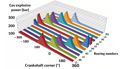
Fig. 4. Cylinder explosive force-crankshaft angle
The crankshaft load mainly comes from the explosive force of gas, and the crankshaft load is the heaviest when the combustion pressure is at its maximum. As shown in Fig. 4, the crankshaft is mainly affected by the gas pressure load from the two cylinders at any time. The crankshaft system has 6 load peaks in one operating cycle, which are work completed by right 1 and left 2 cylinders at -255°, by right 5 and left 4 at -135°, by right 3 and left 1 at -15°, by right 6 and left 5 at 105°, by right 2 and left 3 at 225°, and by right 4 and left 6 at 345°. The position of the cylinder body corresponds to the connecting rod journal of each shaft segment of the crankshaft. The smaller the span of the two cylinders and the farther the equivalent load is from the symmetry center of the crankshaft, and the worse is the effect of the loading. Therefore, the position of -255° is analyzed. The gas explosion pressure on the piston is equivalent to the load on the crankshaft connecting rod journal, and its magnitude and direction are determined by dynamic calculation. Horizontal and vertical displacement constraints are set in each spindle neck, and axial displacement constraints are set in the end of the crankshaft.
Calculation results and analysis
Based on the above conditions, a simple supported beam model, a continuous beam model, and a FEM of crankshaft are established, respectively. The bearing support reaction force is calculated by Matlab and Ansys. Taking the vertical loads on seven main bearings as the object, the calculation results of the three models are studied, as shown in Table 1.
Table 1. Support reaction and support displacement of each bearing
| Bearings | 1 | 2 | 3 | 4 | 5 | 6 | 7 |
|---|---|---|---|---|---|---|---|
| Bearing support reaction by FEM [N] | 53070 | 118420 | 38886 | −6083.8 | −5867.7 | 4883 | −1111.3 |
| Continuous beam bearing support reaction [N] | 62452.65 | 105372.24 | 35072.73 | −5966.52 | −5594.30 | 3850.10 | −904.98 |
| Simply supported beam method bearing support reaction [N] | 131662.4 | 317832.98 | 70533.4 | 0 | 0 | 0 | 0 |
Due to the hyperstatic characteristics of the crankshaft bearing system, changes in the stiffness or relative clearance of one bearing can redistribute the load between adjacent bearings. This coupling is particularly strong at the middle bearings (#3 to #5) with the highest bending curvature of the shaft. As a result, even small deviations in clearance in this region may cause significant changes in bearing reaction forces and support displacement.
Comparing the forces on each main bearing in Table 1, the following conclusions can be drawn: Under the same load, the bearing support reactions obtained by the continuous beam method and by FEM match adequately. In the traditional simple supported beam method, the crankshaft is artificially divided into several sections as static beams supported on two bearings respectively, completely ignoring the influence of adjacent parts on the force of the crank. This is quite different from the actual working conditions, and the error of calculation results is high.
Bearing #2 is located near the rotation axis of the crankshaft, and its corresponding crankshaft angle is -255°. At this point, the corresponding cylinder is the main ignition cylinder. The combined gas-force vector generates a strong bending moment at the second support, resulting in the highest reaction force. The local unloading caused by the multi support hyperstatic characteristics of the crankshaft can have negative reactions. Under strong bending curvature near the mid-span, the shaft slightly lifts from supports #4 and #5, causing them to generate negative reaction forces, and the nearby bearings compensate by increasing the load. However, this assumption ignores the secondary deformation mode of the crankcase, and the calculated bearing reaction force represents an approximation value. Future work will incorporate a more complete flexible installation of the crankshaft-block system.
2.4 Derivation and Calculation of Oil Film Thickness
During the operation of the engine, the crankshaft transmits the load through the lubricating oil film of the main bearings. The oil film is located between the surface of the crankshaft journal and the main bearing hole. The oil film pressure separates the journal from the bearing and bears the load transmitted by the journal to the bearing. The lubrication behavior of each main bearing is governed by hydrodynamic pressure generated by journal rotation and the wedge-shaped lubricant film. The oil-film thickness and eccentricity ratio determine the load-carrying capacity of each bearing, ultimately affecting the support displacement and deformation coordination of the crankshaft-bearing system. These relationships are described directly in the text to reduce redundancy, and the subsequent equation numbering has been adjusted accordingly.
Hydrodynamic Lubrication Governing Equation
The hydrodynamic pressure field in the bearing is governed by the classical Reynolds equation for incompressible, isoviscous lubrication:
\frac{\partial}{\partial x}
\left(
h^3 \frac{\partial p}{\partial x}
\right)
+
\frac{\partial}{\partial z}
\left(
h^3 \frac{\partial p}{\partial z}
\right)
=
6\eta U \frac{\partial h}{\partial x}
\tag{10}
\end{equation}
$$
where h is the local film thickness [m]; p is the oil-film pressure [Pa]; η is the dynamic viscosity [Pa·s]; U is the journal surface velocity [m/s], and x, z are horizontal and axial directions [m], respectively. This equation forms the theoretical basis for the load-bearing capacity of fluid dynamic pressure bearings and is used to link bearing displacement with support reaction forces.
Film geometry and eccentricity
As shown in Fig. 5, the equivalent bearing displacement is expressed as follows:
\Delta y = \delta(1-\chi\cos\varphi)
\tag{11}
\end{equation}
$$
where Δy is a vertical equivalent bearing displacement [m]; δ is the radius clearance of bearings [m]; χ is the eccentricity ratio, and φ is the angle of displacement [rad]. This expression approximates the film profile of journal bearings operating under steady hydrodynamic lubrication.
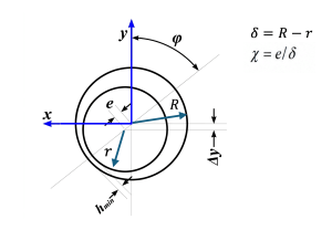
Fig. 5. Position of the journal
Equivalent bearing displacement
The equivalent vertical displacement of a bearing support, denoted Δyi, is determined by the journal center shift caused by oil-film deformation under the applied hydrodynamic load. For a given support reaction Ri, the corresponding eccentricity ratio χ and journal attitude angle φ are obtained from the hydrodynamic pressure distribution, and then the journal center displacement is calculated.
Bearing load-eccentricity relationship
As long as the eccentricity and deflection angle of the journal at the fulcrum are known, the equivalent bearing displacement can be determined. According to the theory of fluid lubrication, the total bearing capacity of oil film is expressed as follows:
F = \frac{\eta \omega dB}{\psi^2} C_p
\tag{12}
\end{equation}
$$
where η is the lubricating oil dynamic viscosity [Pa·s]; B is the bearing width [m]; ψ is the relative gap; d is the journal diameter [m]; Cp is the factor of bearing capacity, and ω is the journal circular velocity [rad/s].
For a single bearing, when the bearing runs stably and other parameters are constant, the bearing capacity coefficient can be determined according to the total bearing load (i.e. bearing support reaction).
C_p = \frac{\psi^2}{\eta \omega dB}F = K \cdot F
\tag{13}
\end{equation}
$$
Since the ratio of width to diameter has been given, the eccentricity χ can be calculated according to Table 2. The scatter plot is shown in Fig. 6.
Table 2. Bearing capacity coefficients
| Eccentricity χ | 0.3 | 0.4 | 0.5 | 0.6 | 0.65 | 0.7 | 0.75 | 0.8 | 0.85 | |
|---|---|---|---|---|---|---|---|---|---|---|
| Bearing capacity factor Cp | 0.0893 | 0.141 | 0.216 | 0.339 | 0.431 | 0.573 | 0.776 | 1.079 | 1.775 |
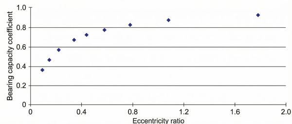
Fig. 6. Scatter diagram of the bearing capacity factor Φ(χ) and eccentricity χ used for curve fitting
To obtain a convenient expression of the bearing capacity factor Φ(χ) as a function of eccentricity χ, several candidate fitting functions (including low-order polynomials, rational functions and exponential functions) are tested using a least-squares criterion based on the tabulated data in Table 2. In these candidates, the exponential function given in Eq. (14) provides the smallest root-mean-square error and the highest coefficient of determination (R²≈0.998) in the eccentricity range from 0.3 to 0.85. In addition, the exponential form preserves the correct monotonic trend and asymptotic behavior of Φ(χ), which is important for avoiding unphysical oscillations in interpolation. Due to these reasons, the exponential function is adopted as the fitting model:
\chi = f(C_p)
=
a e^{b C_p}
+
c e^{d C_p}
\tag{14}
\end{equation}
$$
where a = 0.7947, b = 0.03239, c = −0.6468, d = −3.309.
A shown in Fig. 7, the eccentricity is in the range of 0 to 0.7, and the curve can coincide well with the scatter point. When the eccentricity is greater than 0.7, the curve is consistent with the trend of scatter distribution, with almost the same value. The function can be well consistent with the trend of scatter. Therefore, the fitting function meets the requirement of analysis accuracy.
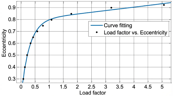
Fig. 7. Fitting curves of χ and Cp
The Gumbel boundary condition is adopted because it is more suitable for finite-length journal bearings under high eccentricity. There is a distinct cavitation region on the unloaded side of the bearing. In contrast, the classical Sommerfeld boundary condition assumes that the circumferential oil film is completely submerged and leads to negative pressure predictions in the cavitated region. This is physically unrealistic. The Reynolds boundary condition modifies the pressure distribution in the cavitated zone. For current system level, its practical implementation in analytical form is more complex. Using the Gumbel boundary condition, the pressure in the cavitation region is set to be equal to the ambient pressure. The range of the bearing area is consistently determined to provide a more realistic estimation of the bearing capacity under heavy load operating conditions. The relation between the deviation angle φ and eccentricity χ can be obtained by Gumbel boundary condition:
\tan\varphi
=
\frac{\bar F_y}{\bar F_x}
=
\frac{\pi}{2}
\frac{\sqrt{1-\chi^2}}{\chi}
\tag{15}
\end{equation}
$$
\cos\varphi
=
\frac{1}{\sqrt{\tan^2\varphi+1}}
=
\frac{4}{\pi^2}
\frac{\chi^2}{1-\chi^2}
\tag{16}
\end{equation}
$$
The joint Eq. (11) gives:
\Delta y
=
\delta
\left(
1-
\frac{4}{\pi^2}
\frac{\chi^3}{1-\chi^2}
\right)
\tag{17}
\end{equation}
$$
From the first n terms of the geometric sequence and the Eq (18):
\sum_{i=1}^n a_1 t^{i-1}
=
\frac{a_1(1-t^n)}{1-t},
\quad \text{when } |t|<1
\tag{18}
\end{equation}
$$
take limit
\sum_{i=1}^{+\infty} a_1 t^{i-1}
=
\frac{a_1}{1-t}
\tag{19}
\end{equation}
$$
let a1 = 4δ / π2, t = χ2, then
\Delta y
=
\delta
–
\frac{4\delta}{\pi^2}
\sum_{i=1}^n \chi^{2i+1}
\tag{20}
\end{equation}
$$
Omitting the higher order infinitesimal term, then:
\Delta y
=
\delta
–
\frac{4\delta}{\pi^2}\chi^3
\tag{21}
\end{equation}
$$
Substituting the crankshaft bearing support reaction and bearing structure parameters solved in Part 1 into Eq. (13) and solving them jointly with Eqs. (14) and (21), the variation of support reaction and support displacement in the vertical direction of each bearing is obtained. The calculation results are shown in Table 3.
Table 3. Bearing support load and displacement
| Bearings | 1 | 2 | 3 | 4 | 5 | 6 | 7 |
|---|---|---|---|---|---|---|---|
| Bearing load [N] | 53070 | 118420 | 38886 | -6083.8 | -5867.7 | 4883 | -1111.3 |
| Support displacement [mm] | 0.0243 | 0.0168 | 0.0259 | -0.0546 | -0.0544 | 0.0449 | -0.0496 |
According to Eq. (21), the displacements of crankshaft bearings under harsh working are calculated. It is found that the deformation state of the crankshaft system has a large optimization space. Lubrication analysis is conducted under a quasi-static assumption by taking the worst-case crank angle (-255°) and treating the oil film as being in a steady hydrodynamic equilibrium with the instantaneous bearing load. This method is widely used for preliminary design and parametric analysis, but it does not capture the full transient and TEHD behavior of dynamically loaded bearings. Extending the present model to a time-resolved TEHD analysis can more detailed evaluate the minimum film thickness and temperature increase in an engine cycle. This is also the subject of our future work.
3 RESULTS AND DISCUSSION
3.1 Crankshaft-Bearing System Structure Optimization
This section applies modern design theory, MATLAB software and practical application to optimize the shaft system, and achieve better stiffness match between the crankshaft and the supporting bearing.
In theory, when the crankshaft is not deformed by force, the displacement of each support should be consistent. The more discrete the displacement of each support, the greater the deformation of the crankshaft. Therefore, the variance value of each support displacement can be set as the objective function for evaluating the deformation coordination degree of the crankshaft-bearing system.
The optimization objective is to improve the deformation coordination of the crankshaft-bearing system by minimizing the variance of the support displacements among the main bearings. Therefore, the objective function is defined as follows:
F(X)
=
\sqrt{
\sum_{i=1}^7
\Delta y_i – \Delta \bar y^2
}
\tag{22}
\end{equation}
$$
where ∆yi is the ith bearing displacement [mm], and ∆ȳ average displacement of each support [mm].
It can be seen from Eqs. (11) and (12) that there are many parameters affecting the displacement of bearing support. In engineering practice, these parameters such as lubricating oil dynamic viscosity, crankshaft speed, bearing span and crankshaft shape cannot be adjusted. Bearing clearance has a significant impact on the maximum temperature and maximum friction power loss of the main bearing [25]. Therefore, the relative gap ψ is selected as the optimization variable.
The conditions that limit the range of design variables based on actual requirements in engineering design are called constraints. Parameter control here is achieved by adjusting the size tolerance of the crankshaft journal. Before optimization, each main bearing is supported with equal stiffness, and each bearing journal adopts
H7/e8 fit. The crankshaft journal will tilt under the combined action of external load and bearing constraints. To avoid the stress increase caused by scraping bearing and the oil film deflection caused by the journal tilt, the journal tilt should be controlled. Based on the principle of linear superposition of small deformation, the inclination angle of journal Li at bearing i can be obtained as follows:
\begin{gathered}
\theta_i
=
\theta_{iP_i}
+
\theta_{iM_i}
+
\theta_{iM_{i-1}}
+
\theta_{iq_i}
+
\theta_{iY} \\
=
\frac{P_i a_i(L_i^2-a_i^2)}{6E_i I_i L_i}
+
\frac{M_i}{3E_i I_i}L_i
+
\frac{M_{i-1}}{6E_i I_i}L_i \\
+
\frac{q_i L_i^3}{24E_i I_i}
+
\frac{Y_i-Y_{i-1}}{L_i}
\leqslant [\theta]
\end{gathered}
\tag{23}
\end{equation}
$$
The crankshaft journal is 98 mm. The relative clearance recommended in the design standard JB/ZQ 4614-2006 (Table 4) is taken into account [26]. JB/ZQ 4614-2006 specifies the recommended fit clearances for sliding bearings under nominal diameter and operating conditions. The recommended clearances adopted are consistent with the ISO 286-1:2010 system of limits and fits for hole-shaft pairs (such as H7/e8 and H7/f7 fits for bearing-journal assemblies. Therefore, the clearance ranges in Table 4 can also be interpreted in the framework of the ISO 286-1:2010 limits and fits system [27].
ψi ∈ [0.007, 0.0016], i = 1, 2, 3, 4, 5, 6, 7.
Table 4. Bearing piston engine and the oil film bearing clearance
| Bearing diameter [mm] | Minimum clearance | Average clearance | Maximum clearance |
|---|---|---|---|
| 80-120 | 0.072 | 0.117 | 0.161 |
The mathematical model of optimal design of crankshaft shafting can be expressed as optimization objective:
\min F(X)
=
\sqrt{
\sum_{i=1}^{7}
\left(
\Delta y_i – \Delta \bar y
\right)^2
}
\tag{24}
\end{equation}
$$
constraint condition:
\begin{aligned}
\text{s.t.}\;\;
g(X)
&=
\frac{P_i a_i(L_i^2-a_i^2)}{6E_i I_i L_i}
+
\frac{M_i L_i}{3E_i I_i}
+
\frac{M_{i-1}L_i}{6E_i I_i} \\
&\quad
+
\frac{q_i L_i^3}{24E_i I_i}
+
\frac{Y_i-Y_{i-1}}{L_i}
\leqslant [\theta]
\end{aligned}
\tag{25}
\end{equation}$$
optimization variable, where ψmin ≤ ψ1 ~ ψ7 ≥ ψmax. The optimization problem is solved using the sequential quadratic programming (SQP) algorithm implemented in MATLAB’s fmincon solver. SQP is highly suitable for constrained nonlinear optimization tasks with smooth objective functions, and provides fast convergence in problems with fewer design variables.
The PSO algorithm is also used to cross-check the SQP result and verify that the identified optimum is not a local minimum. The objective decreases monotonically and stabilizes after 20 iterations, confirming convergence.
Considering the selection range of relative clearance recommended in the design standard of plain bearings, the bearing support displacement obtained through optimization calculation is shown in Table 5.
Table 5. Journal bearing with selection and optimization results
| Bearings | 1 | 2 | 3 | 4 | 5 | 6 | 7 | Tolerance |
|---|---|---|---|---|---|---|---|---|
| Recommended fit | H7/e8 | H7/e8 | H7/f7 | H7/f7 | H7/f7 | H7/e8 | H7/e8 | |
| The amount of support displacement before optimization [mm] | 0.0243 | 0.0168 | 0.0259 | -0.0546 | -0.0544 | 0.0449 | -0.0496 | 0.0019 |
| The amount of support displacement after optimization [mm] | 0.0243 | 0.0168 | 0.0222 | -0.0386 | -0.0385 | 0.0449 | -0.0496 | 0.0013 |
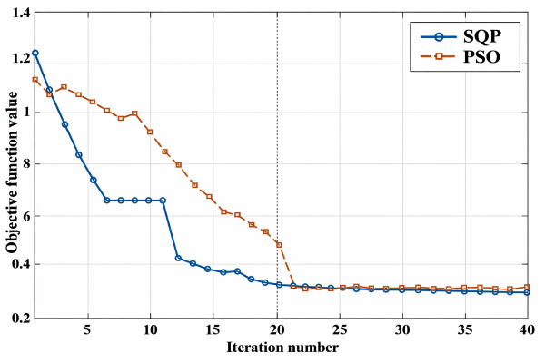
Fig. 8. Convergence history of SQP and PSO algorithms
To improve the deformation coordination state of crankshaft shafting, different journal bearings are selected to change the equal stiffness support and increase the stiffness of each support in the middle position. A quantitative comparison of the bearing support displacements before and after optimization is provided in Table 5. The results show that the deformation coordination of the crankshaft-bearing system is significantly improved after optimization, as evident from the systematic reduction in bearing displacement magnitudes in all main bearings. In particular, the maximum tilt deformation at the most critical shaft segment is reduced by about 18 % after optimization. This indicates a clear improvement in local stiffness matching and support compatibility. In addition, the overall deformation coordination evaluated based on the displacement tolerance between the main bearing supports has increased by about 31%. This indicates that the support reaction force distribution along the crankshaft is more uniform, and the deformation incompatibility is reduced.
The high performance of the optimized clearance configuration can be explained by the interaction between bearing stiffness, shaft bending curvature, and hydrodynamic film formation. In areas with high bending curvature of the crankshaft, slightly reduced clearance increases local support stiffness and limits journal misalignment. In areas with lower curvature, slightly larger clearance allows the system to redistribute loads more evenly on adjacent bearings. This coordinated effect suppresses deformation incompatibility, stabilizes the oil-film geometry, and enhances lubrication robustness. These mechanisms collectively explain why the optimized clearance pattern can provide more favorable structural and lubrication characteristics than the baseline configuration.
Theoretically, the improvement in deformation coordination can be explained by the redistribution of the curvature of the beam. When the bearing stiffness is uniform, areas with high bending curvature will generate large local support displacement gradients. By selectively modifying clearance, the effective hydrodynamic stiffness of middle bearings increases, thereby suppressing curvature amplification. This phenomenon can be explained by treating each bearing as a nonlinear spring, whose stiffness is determined by the lubrication-film geometry. The optimized configuration can reduce stiffness discontinuities and stabilize load transfer between adjacent spans. In addition, the reduction of displacement variance implies that the alignment between journal axis and bearing axis is improved. The improved alignment can enhance oil-film stability and reduce the risk of edge loading. Therefore, optimization helps to improve structural reliability, lubrication safety margin, deformation coordination and lubrication performance. These improvements promote more uniform load distribution along the crankshaft, reduce local wear, and lower the risk of edge loads and lubrication failures. In addition, the proposed tolerance-based optimization strategy is fully compatible with standard manufacturing practices and provides a practical, low-cost method for improving the durability and lubrication robustness of production engines.
Although this study does not include bench-test validation, the predicted improvement in deformation coordination and oil-film safety margin is consistent with experimental findings in TEHD and elastohydrodynamic studies [17,18,28]. Future work will incorporate experimental measurements of bearing deformation and oil-film thickness to directly verify this optimization strategy.
3.2 Structural–Lubrication Coupling Analysis
Although Section 2.4 introduces the lubrication formula, its role in the final solution needs to be clarified. The fluid dynamic lubrication model is not an isolated frictional calculation, but a stiffness coupling mechanism that links the bearing reaction force and support displacement.
According to Eq. (13), the bearing reaction is directly related to the bearing capacity coefficient Φ(χ), which is determined by the eccentricity ratio χ. Through the fitted exponential relation, variations in bearing clearance will change the effective hydrodynamic stiffness of each support. This modified the deformation coordination equation, thereby redistributing the bearing reaction force.
Before optimization, due to the large bending curvature, the intermediate bearings (# 3-# 5) showed relatively high eccentricity. This leads to a decrease in local oil film thickness and uneven load distribution. After optimization, the adjusted relative clearances reduce the eccentricity gradient along the shafting, resulting in a more uniform hydrodynamic stiffness distribution, reducing peak eccentricity at critical span, and improving the consistency of oil-film load-carrying.
The coupling effect explains why the deformation coordination has increased by 31 %. The optimization cannot only change geometric clearance, but also reshape the structural and tribological interaction mechanism. Therefore, although the lubrication model is not solved dynamically in a full TEHD sense, it directly affects the final support reaction distribution and should be regarded as an integral component of the structural optimization framework.
4 CONCLUSIONS
The deformation coordination of an engine crankshaft-bearing system is investigated and a tolerance-based method is presented to improve stiffness matching. The main findings are drawn as follows:
1. The continuous beam theory is used to calculate the bearing capacity, which is different from the traditional simply supported beam method;
2. The fluid dynamic lubrication formula is integrated into a stiffness coupling mechanism that connects the bearing reaction force and support displacement. By integrating the lubrication model into the deformation coordination framework, the interaction between structure and tribology is explicitly considered, achieving coordinated optimization of stiffness matching and oil film load capacity;
3. Combined with the crankshaft deformation coordination equation, the maximum deformation position and deformation degree of crankshaft at a certain time can be determined by using the calculated support displacements. Taking the tolerance of each support displacement as the optimization target and the relative clearance as the optimization variable, the structure is optimized. This method has the advantages of clear intuitive meaning and easy operation, which provide a reference for the overall evaluation of crankshaft deformation coordination;
4. The coupling effect between structure stiffness and friction lubrication of engine crankshaft-bearing system is studied, avoiding the artificial separation of the crankshaft-bearing system. This optimization method can provide practical guidance for improving the stiffness matching between crankshaft and bearings. It also provides measurable benefits in oil-film load-carrying capacity and wear reduction, thereby supporting real-engine applications.
References
- Skulić, A., Bukvić, M. Tribological properties of piston-cylinder set in internal combustion engines. Appl Eng Letter 1 29-33 (2016).
- Chen, Y., Hu, Z., Zhang, H., Shi, Z., Gu, F. Tribology and characterization of dynamically-loaded crankshaft main bearings with surface roughness. Mechanis Mache Sci 151 47-62 (2024) DOI:10.1007/978-3-031-49413-0_5.
- Cho, I.S., Jung, J.Y. The friction characteristics of the journal bearing in a reciprocating compressor for refrigeration and air conditioning systems. J Mech Sci Technol 28 1473-1480 (2014) DOI:10.1007/s12206-014-0132-4.
- Rong, B. Efficient dynamics analysis of large-deformation flexible beams by using the absolute nodal coordinate transfer matrix method. Multibody Syst Dyn 32 535-549 (2014) DOI:10.1007/s11044-013-9402-7.
- Choi, J., Kim, S.S., Rhim, S.S., Choi, J.H. Numerical modeling of journal bearing considering both elastohydrodynamic lubrication and multi-flexible-body dynamics. Int J Automot Technol 13 255-261 (2012) DOI:10.1007/s12239-012-0022-7.
- Bai, S.Y., Liu, W.B., Lu, H.L., Zhang, T.L. Strength calculation comparison between continuous beam method and finite element method of the 3300hp quintuple cylinders fracturing pump crankshaft. Mech Resear Appl 33 25-29 (2020).
- Jorwekar, P.P., Birari, Y.V., Nadgouda, M.M. Cylinder head gasket contact pressure simulation for a hermetic compressor. International Compressor Engineering Conference (2006) Purdue.
- Takahashi, M., Isarai, R., Hara, H. Measurement of piston using the new digital telemeter. SAE Int J Engines 6 577-586 (2013) DOI:10.4271/2013-01-1708.
- Matsuo, K., Kiga, S., Murata, S., Satou, N., Miyake, H., Suzuki, K. et al. Reduction of piston system friction by applying a bore circularity machining technology to the cylinder block.SAE TecPap 2005-01-1656 (2005) DOI:10.4271/2005-01-1656.
- Antoni, N., Gaisne, F. Analytical modeling for static stress analysis of pin-loaded lugs with bush fitting. Appl Math Model 35 1-21 (2011) DOI:10.1016/j.apm.2010.05.002.
- Zhang, X.Q., Wu, J., Zeng, Z.X., Gao, W.Z., Chen, K.P. Finite element analysis of the combination structures for cylinder head and block of a four-cylinder gasoline engine. Mech Sci Tech Aerosp Eng 34 32-36 (2015) DOI:10.13433/j.cnki.1003-8728.2015.0107. (in Chinese)
- Zhai, X.M., Tian, X.W., Zhang, C.B., Li, Y.J., Liu, S., Cui, Y. Coupling characteristics of lubrication and flexible multibody dynamics of piston-liner pairs in diesel engines. J Shanghai Jiaotong Uni 58 324-332 (2024) DOI:10.16183/j.cnki.jsjtu.2022.357. (in Chinese)
- Bi, Y.H., Chen, S.J., Yao, G.Z., Chen, M.Y., Shen, L.Z., Xia, K.L. Study on the influence of coolant flow uniformity on the thermal deformation of cylinder liner. Chin J Auto Eng 43 34-43 (2021) DOI:10.19562/j.chinasae.qcgc.2021.01.005. (in Chinese)
- Tian, J.L., Zhang, C.P., Liu, W.K., Wang, P. Dynamics simulation of torsional vibration of crankshaft of diesel engine. Mod Manuf Eng 10 96-101 (2017) DOI:10.16731/j.cnki.1671-3133.2017.10.018. (in Chinese)
- Deng, M., Sun, J., Fu, Y.H., Gui, C.L. Thermoelastohydrodynamic lubrication analysis of bearing considering shaft deformation and surface roughness. J Mech Eng 46 95-101 (2010) DOI:10.3901/JME.2010.15.095. (in Chinese)
- Zhang, L., Lu, X.Q., Zhao, B., Zhong, N., Huang, F.Z., Liu, C.P. Coupling modeling research on tribological and dynamical behaviors of main bearing of diesel engine considering crankshaft deformation and block distortion. Ship Eng 41 146-149 (2019) DOI:10.13788/j.cnki.cbgc.2019.S1.034. (in Chinese)
- Yu, C.Y., Guo, J., Zhao, J., Zhang, H., Wang, R.Z. On elastohydrodynamic lubrication and dynamic characteristics of multi-cylinder diesel engine crankshaft-bearing. Ship Boat 33 85-94 (2022) DOI:10.19423/j.cnki.31-1561/u.2022.02.085. (in Chinese)
- Wei, L.D., Cao, C., Zhang, D.P., Li, J.M. Study on main bearing friction of marine diesel engine based on thermal elasto-hydrodynamic hybrid lubrication. Lubr Eng 46 1-8 (2021) DOI:10.3969/j.issn.0254-0150.2021.09.001. (in Chinese)
- Shao, K., Wang, G.D., Bi, F.R. Analysis of Factors Affecting lubrication performance of crankshaft main bearing considering thermal effect. J Mech Trans 46 119-124 (2022) DOI:10.16578/j.issn.1004.2539.2022.10.018. (in Chinese)
- Gao, Y.M., Sun, J., Li, B., Fu, Y.Y., Zhang X., Zhu, J.X. A review of the coupling researches on dynamical and tribological behaviors of crankshaft-bearing system of internal combustion engines. Small Int Comb Eng Motorcyc 49 84-91 (2020). (in Chinese)
- Wang, D.C., Xiang, J.H., Liu, J., An, X.H., Wang, J.L., Liu, K. Study on heat effect mechanism and rules of crankshaft bearing of internal combustion engine. Global Conference on Robotics, Artificial Intelligence and Information Technology (2022) 522-528 DOI:10.1109/GCRAIT55928.2022.00113.
- Tong, V.C., Hwang, J.H., Shim J.Y., Oh, J.S., Hong, S.W. Multi-objective optimization of machine tool spindle-bearing system. Int J Precis Eng Manuf 21 1885-1902 (2020) DOI:10.1007/s12541-020-00389-7.
- Zhan, Z.Q., Fang, B., Wan, S.K., Hong, J., Li, X.H. A novel approach to the thermal-deformation coupling calculation of the high-speed spindle-bearing system. Int J Mech Mater Des 19 391-406 (2022) DOI:10.1007/s10999-022-09634-5.
- Karimaei, H., Chamani, H. Effect of crankshaft and crankcase material stiffness on load distribution in main bearings. Int J Automot Mech Eng 15 5941-5956 (2018) DOI:10.15282/ijame.15.4.2018.16.0453.
- Shao, K., Wang, G.D., Bi, F.R. Influence of bearing structural parameters on the lubrication performance of crankshaft main bearing. Lubr Eng 48 9-15 (2023) DOI:10.3969/j.issn.0254-0150.2023.07.002.
- JB/ZQ 4614-2006. Sliding bearing fit clearance. China Heavy Machinery Industry Association (2006).
- ISO 286-1:2010. Geometrical product specifications (GPS)-ISO code system for tolerances on linear sizes. Part 1: Basis of tolerances, deviations and fits. International Organization for Standardization (2010) Geneva.
- Sun, J., Cai, X.X., Liu, L.P., Gui, C.L. Analysis of elastohydrodynamic lubrication of crankshaft bearing considering deformation of engine block and crankshaft. Trans of CSICE 28 275-280 (2010) DOI:10.16236/j.cnki.nrjxb.2010.03.014. (in Chinese)