

1 INTRODUCTION
As a common vegetable, onions are highly regarded for their unique taste and rich nutritional value [1]. With rising agricultural labor costs and the increasing demand for large-scale cultivation, traditional manual transplanting methods have become increasingly challenged by issues such as unstable planting quality, low operational efficiency, and high labor intensity [2]. Therefore, the development of efficient and structurally simple onion transplanting machinery has become an urgent need. According to the agronomic requirements of onion seedling transplantation, such machinery must satisfy specific trajectory control requirements during the transplanting process. Specifically, during seedling insertion, the end-effector must maintain stable motion, an optimal speed, and consistent planting depth, imposing stringent demands on the kinematic performance of the mechanism [3,4].
In the current agricultural machinery landscape, onion transplanters are broadly classified into handheld, semi-automatic, and fully automatic systems. Nandede et al. [5] developed a low-cost handheld single-row transplanter featuring a compact design with a duckbill mechanism (a spring-loaded seedling gripper), where the operator controls gripper motion via a manual lever. However, this design relies entirely on physical labor, achieving a maximum transplanting rate of only 250 to 300 plants per hour – far below the 1500 to 2000 plants/hour capacity of semi-automatic models – and imposes significant physical strain on operators. Studies [6,7] focused on the needs of small-scale farmers in Bangladesh and developed a small-scale onion transplanter suitable for local conditions. In particular, Nasim et al. [7] optimized the rotational speed of a gear-driven rotary planting mechanism (10 rpm to 15 rpm). Under these conditions, the mechanism achieved maximum velocity and acceleration of 1032 mm/s and 6501 mm/s², respectively. At a higher rotational speed of 60 rpm (2π rad/s), its power consumption was 35.4 W, while the single-unit and double-unit assemblies achieved transplanting rates of 60 and 120 seedlings per minute. Habineza et al. [8] indicates that semi-automatic transplanters typically combine manual seedling raising with automated planting, with common forms including manual-pulled, ride-on, and tractor-mounted types. In contrast, fully automatic transplanters are capable of automatically picking seedlings, transferring them onto a conveyor, and continuously completing the planting process. However, onion transplanting systems still face key challenges in trajectory control, including motion reversal interference, end-effector posture deviation, and structural complexity.
In recent years, various transplanting mechanisms such as duckbill type [9], five-bar linkage [10], and crank-rocker linkage [11] have been widely studied. Researchers have utilized tools like ADAMS and MATLAB to optimize the transplanting trajectories.
Meanwhile, non-circular gears, due to their non-uniform transmission characteristics, have been extensively applied in rice and vegetable transplanters [12-14]. Zhao et al. [15] put forward a new high-order non-circular gear mechanism that is appropriate for scallion seedling transplanting, and achieved parameter optimization through program-based modeling and motion simulation. Shi et al. [16] designed a non-circular gear-driven forward compensation speed mechanism and developed a new type of direct-planting corn seeder. Xu et al. [17], Yu et al. [18], and Xin et al. [19] also applied non-circular gears extensively in transplanting mechanisms to optimize motion characteristics and improve the efficiency and precision of seedling pickup and planting. Overall, the variable-speed transmission capability of non-circular gears has, to some extent, enhanced the operational performance of transplanting mechanisms. In traditional four-bar transplanting mechanisms, elliptical gears are commonly used as driving elements because they can provide periodic variable-speed output. However, the transmission ratio of standard elliptical gears is limited by their symmetrical design, which restricts precise adjustment of the time ratio between the working and return phases of the transplanting mechanism. This limitation further constrains the potential for optimizing trajectory and motion characteristics [20].
To overcome symmetry limitations, researchers have introduced the concept of denatured elliptical gears. By incorporating a denaturation coefficient, the shape of the elliptical pitch curve can be adjusted to exhibit asymmetric transmission characteristics within a single rotational cycle, thereby providing a new approach for precise control of mechanism motion laws [21-22]. Meanwhile, another class of non-circular gears based on the Pascal spiral has also demonstrated significant application potential in transplanting mechanisms. Studies indicate that, compared with other conventional non-circular gears, Pascal spiral gears offer distinct advantages in achieving variable transmission ratios and non-uniform motion transmission between two shafts [23].
At the level of multi-objective optimization methodologies, genetic algorithms (GA) and their improved variants, such as non-dominated sorting genetic algorithm II (NSGA-II), have been widely applied to parameter optimization of mechanical systems due to their strong capability in solving complex and nonlinear engineering optimization problems. Cha et al. [24] successfully integrated multibody dynamic simulation with genetic algorithms to optimize the geometric parameters of a planetary gear transmission, resulting in significant improvements in its dynamic performance. In the field of agricultural machinery, such algorithms have likewise been effectively employed for mechanism optimization; Zhao et al. [25] used the NSGA-II algorithm to obtain a set of mechanism parameters that better satisfy agronomic requirements.
Building upon this research foundation, this study proposes a novel approach that employs denatured Pascal limacon gears as the transmission driver, replacing conventional elliptical gears. A kinematic model of the mechanism is established. By analyzing the influence of various mechanism parameters on the trajectory and velocity of the transplanter’s end-effector, the study defines multiple performance objectives, including planting depth, trajectory, and the zero-speed seedling release point. The NSGA-II multi-objective genetic algorithm is then utilized to optimize the key mechanism parameters. This integrated approach comprehensively enhances the precision, stability, and efficiency of the transplanting operation. The work provides a theoretical foundation and technical guidance for developing high-speed, precise, and cost-effective onion transplanting equipment.
2 MATERIALS AND METHODS
2.1 Design Requirements for the Planting Mechanism
Figure 1 illustrates the motion trajectory of the planter unit in the parallelogram transplanting mechanism during operation, specifically Fig. 1a depicts the circular trajectory of the planter when the machine is stationary, while Fig. 1b shows that the actual trajectory during forward movement is cycloidal. Based on existing research findings on onion transplanters, this transplanting mechanism must meet the following agronomic requirements: The transplanting speed should be maintained at 70 to 80 plants per minute; the planting spacing should be controlled within 200 to 400 mm; the average planting depth should be maintained at 25 mm. When the duckbill reaches the highest point of its trajectory (point a) to pick up seedlings, its velocity should be zero; and when the duckbill releases seedlings into the soil at point c, both its velocity and acceleration must be zero.
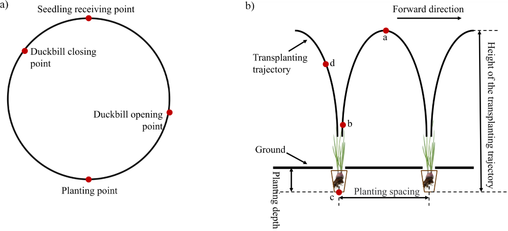
Fig. 1. Movement trajectory of the planter: a) static trajectory, and b) dynamic trajectory
2.2 Structural Design and Working Principle
As shown in Fig. 2a, during the operation of the planting mechanism, the power input system synchronously drives the end-effector control device and the gear transmission mechanism via a chain and sprocket drive. The end-effector control device regulates the opening and closing timing of the duckbill jaws via a cam-driven mechanism [26]. Concurrently, the driving denatured Pascal limacon gear transmits the input uniform rotational motion to the driven denatured Pascal limacon gear via variable-ratio meshing, achieving a rotational speed transformation. A spur gear, rigidly connected coaxially to the driven worm gear, transfers the variable-speed rotation to the double cranks of the parallelogram mechanism through a subsequent spur gear transmission pair. The coordinated operation of the double cranks results in a non-uniform periodic reciprocating motion of the connecting rod. The duckbill end-effector, rigidly attached to the coupler link’s distal end, generates a horizontal kinematic component during synthesis that is equal in magnitude but opposite in direction to the chassis’ forward velocity vector. This relative velocity nullification at soil entry enables zero-speed seedling insertion, ensuring stable and upright planting.
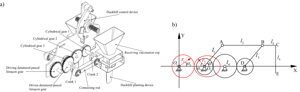
Fig. 2. Overall structure diagram of the planting device
2.3 Kinematic Model of Planting Mechanism
Figure 2b presents the fundamental structure of the planting mechanism. A XO1Y Cartesian coordinate system is established, designating point O1 as the origin, the horizontal line as the X-axis, and the vertical line as the Y-axis, as illustrated in Fig. 2b. Table 1 enumerates the relevant parameters along with their definitions, which are also indicated in Figs. 2a.
Table 1. Relevant parameters and their meanings
| Symbol | Explanation |
|---|---|
| r1, r2 | Pitch radius of denatured Pascal limacon gear, [mm] |
| α | Initial phase angle of crank O2A |
| α1, α2 | Angular displacement of the driving and driven denatured Pascal limacon gear, [°] |
| l1 | Length of crank O2A |
| l2 | The length of the connecting rod AB, [mm] |
| l3 | Length of crank DB, [mm] |
| l5 | The length of the connecting rod BC, [mm] |
| l6 | Height of the duckbill planting tool, [mm] |
2.4 Theoretical Analysis of Denatured Pascal Limacon Gear
2.4.1 Pitch Curve Equation of a Gear Pair
Figure 3 illustrates the generation principle of an arbitrary Pascal limacon gear. In Fig. 3, generating circle 1 is centered at point (b/2, 0) with a radius b/2. Trajectory 2, defined as the path of a point located at a radial distance l from a point on this circle, forms a Pascal curve.
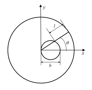
Fig. 3. Pascal’s curve
By adjusting the ratio of b to l, the shape of the limacon line can be changed: when b/l is small, the limacon approaches a circle, as shown in Fig. 4a; when b/l increases, the curve exhibits distinct “limacon” characteristics, that is, with one side bulging outward and the other side curving inward, as shown in Fig. 4b (when b = l, the curve is heart-shaped; when b > 1, the curve shows a loop-like phenomenon) [27].
According to geometry, this trajectory follows a cosine pattern and the expression for this point’s trajectory can be represented as:
r=b\cos\theta+l
\tag{1}
\end{equation}$$
In the polar equation of the Pascal curve, b represents the diameter of the generating circle, and l denotes the offset distance from a point on the circle’s circumference.
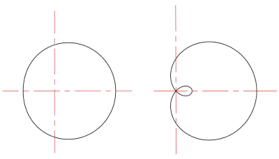
Fig. 4. The line types of the node curve at different ratios of b to l
The denatured Pascal limacon gear used in this paper introduces a denaturation coefficient into the basic Pascal limacon gear pitch curve equation to asymmetrically adjust the gear transmission ratio curve, thereby generating asymmetric speed changes within one rotation cycle. This design is beneficial for the planting mechanism to have different speed changes during the soil insertion stage and the lifting stage, that is, deceleration during insertion and acceleration during lifting, thereby reducing the impact on the seedlings and the soil.
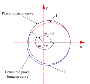
Fig. 5. Pitch curve of the denatured Pascal limacon gear
The denatured Pascal limacon gear line consists of two curve segments. By introducing a denaturation coefficient, the periodic variation of the transmission ratio of the non-circular gear changes from symmetry about φ = π to an asymmetric pattern. In Fig. 5, Ⅰ represents the basic Pascal limacon gear pitch curve. At φ = π, the curve is divided into two segments. In the first segment 0 ≤ φ ≤ π, the denaturation coefficient m11 is introduced and the interval becomes 0 ≤ φ ≤ (π/m11). Similarly, in the second segment π ≤ φ ≤ 2π, the denaturation coefficient m11 is introduced and the interval is adjusted to (π/m11) ≤ φ ≤ 2π. Variables m11 and m12 are the coefficients of variation for the two segments, respectively, and m11 and m12 are required to satisfy the following expressions:
\left\{
\begin{aligned}
&m_{11}>\frac{1}{2},\\
&\frac{\pi}{m_{11}}+\frac{\pi}{m_{12}}=2\pi.
\end{aligned}
\right.
\tag{2}
\end{equation}$$
Based on geometric modeling and numerical analysis, the mathematical equations for the pitch curve of the denatured Pascal limacon gear are established as shown below:
r_1(\varphi_1)=
\left\{
\begin{aligned}
&b\cos(m_{11}\varphi_1)+l,
&&0\leq\varphi_1\leq\frac{\pi}{m_{11}},\\
&b\cos\!\left(m_{12}(2\pi-\varphi_1)\right)+l,
&&\frac{\pi}{m_{11}}\leq\varphi_1\leq2\pi.
\end{aligned}
\right.
\tag{3}
\end{equation}$$
In Eq. (3), φ1 represents the initial angle. To ensure the continuous transmission of non-circular gears, it is necessary to ensure that the center distance between the conjugate gear pitch curves remains constant at each angular position, that is, the sum of the radii of the pitch curves of the driving gear and the driven gear is always equal to a fixed center distance [28]. According to the gear meshing principle and transmission characteristics, the pitch curve equation of the non-circular gear 2 that is conjugate to it is:
\left\{
\begin{aligned}
&r_2(\varphi_2)=a-r_1(\varphi_1),\\
&\varphi_2(\varphi_1)
=\int_0^{\varphi_1}\frac{1}{i_{12}}\,d\varphi_1
=\int_0^{\varphi_1}
\frac{r_1(\varphi_1)}
{a-r_1(\varphi_1)}\,d\varphi_1.
\end{aligned}
\right.
\tag{4}
\end{equation}$$
2.4.2 Closure Conditions and Convexity–Concavity Inspection of the Gear Pair
Based on the angular relationship between the driving gear and the driven gear, the closed condition of the pitch curve can be obtained. If the center distance of the gear pair is a, the closure condition for the pitch curve of the non-circular gear 2 that is conjugate to the denatured Pascal limacon gear is:
\frac{2\pi}{n_2}
=
\int_0^{2\pi}
\frac{r_1(\varphi_1)}
{a-r_1(\varphi_1)}
\,d\varphi_1
=
\int_0^{\frac{\pi}{m_{11}}}
\frac{
b\cos(m_{11}\varphi_1)+l
}{
a-\left(b\cos(m_{11}\varphi_1)+l\right)
}
\,d\varphi_1
\tag{5}
\end{equation}$$
where n2 denotes the order of the driven gear. Given the arc length formula for the non-circular gear pitch curve and the condition of uniform tooth distribution, the perimeter L of the pitch curve must satisfy the following condition:
L=
\int_0^{2\pi}
\sqrt{r^2+\left(r’\right)^2}
\,d\varphi
=
\pi m Z
\tag{6}
\end{equation}$$
where m is the gear module and Z is the number of teeth on the gear. The pitch curve equation of the modified Pascal’s limacon gear indicates that its arc length comprises two distinct segments. Accordingly, the lengths of the two pitch curve segments, denoted as l11 and l12, relate to the total perimeter L through the following expressions:
\begin{aligned}
L
&=l_{11}+l_{12}\\
&=
\int_0^{\frac{\pi}{m_{11}}}
\sqrt{
b^2+l^2+2bl\cos(m_{11}\varphi_1)
+\left(m_{11}^2-1\right)b^2\sin^2(m_{11}\varphi_1)
}
\,d\varphi_1\\
&\quad+
\int_{\frac{\pi}{m_{11}}}^{2\pi}
\sqrt{
b^2+l^2+2bl\cos\!\left(m_{12}(2\pi-\varphi_1)\right)
+\left(m_{12}^2-1\right)b^2
\sin^2\!\left(m_{12}(2\pi-\varphi_1)\right)
}
\,d\varphi_1\\
&=\pi m Z
\end{aligned}
\tag{7}
\end{equation}$$
Therefore, meeting these formulas enables precise transmission of the denatured Pascal limacon gear pair [29,30]. Unlike circular gears, non-circular gears have a pitch curve with varying radii of curvature at each point. Using the curvature formula from differential geometry for parametric curves, the radius of curvature at any point on the non-circular gear’s pitch curve is given by:
\rho=
\frac{
\left(r^2+\left(\frac{dr}{d\varphi}\right)^2\right)^{3/2}
}{
r^2+2\left(\frac{dr}{d\varphi}\right)^2
-r\frac{d^2r}{d\varphi^2}
}
\tag{8}
\end{equation}$$
where dr/dφ and d2r/dφ2 denote the first and second derivatives of r with respect to φ, respectively. According to differential geometry, by analyzing the radius of curvature at each point on the denatured Pascal limacon gear’s non-circular pitch curve, it can be concluded that when the curvature radius ρ > 0, the pitch curve is convex; when ρ < 0, the curve is concave. By analyzing the radius of curvature at each point along the pitch curve of the denatured Pascal limacon gear, the criterion for avoiding concave points on the driving gear’s pitch curve is obtained as follows:
\left\{
\begin{aligned}
&\left[1-\left(m_{11}^2+1\right)k\right](1-k)>0,\\
&\left[1-\left(m_{12}^2+1\right)k\right](1-k)>0,\\
&k=\frac{b}{l}.
\end{aligned}
\right.
\tag{9}
\end{equation}$$
Similarly, the condition for determining that the driven conjugate non-circular curve that meshes with the active denatured Pascal limacon gear does not undergo inward concave denaturation is:
\left\{
\begin{aligned}
&\left(m_{11}^2+1\right)k^2
+\left(2-m_{11}^2\right)k
-m_{11}^2k^3+1>0,\\
&\left(m_{12}^2+1\right)k^2
+\left(2-m_{12}^2\right)k
-m_{12}^2k^3+1>0,\\
&k=\frac{b}{l}.
\end{aligned}
\right.
\tag{10}
\end{equation}$$
2.4.3 Construction of the Three-Dimensional Model of the Gear Pair
By investigating the generation principle of the denatured Pascal limacon gear, this paper primarily makes use of the closure condition and center distance equation, using a numerical approach based on solving systems of nonlinear equations. Combined with numerical integration and nonlinear optimization of an objective function, the method iteratively solves for the main design parameters b and l of the denatured Pascal limacon gear through initial value estimation. Due to the unique structure of non-circular gears, their design involves complex kinematic constraints, and the generation of the tooth profile remains a key challenge. Therefore, this study employs a tooth profile generation method based on coordinate transformation matrices and numerical envelope principles. This approach simulates the conjugate generating motion between standard cutting tools and denatured Pascal limacon gear blanks through numerical computation, transforming the continuous tooth envelope problem into a discrete high-precision point set for solution. The resulting point set data can be directly imported into computer-aided design software. Through spline curve fitting and solid modeling, the denatured Pascal limacon gear three-dimensional model shown in Fig. 6 is ultimately generated.
Fig. 6. Three-dimensional model of the denatured Pascal limacon gear pair
2.5 Analysis of the Transmission Characteristics of the Denatured Pascal limacon gear
To clarify the kinematic analysis of the denatured Pascal limacon gear pair, a fixed coordinate system Oxy is established with its origin at the rotation center O of the driving gear, as shown in Fig. 7. In the Fig. 7, 1 represents the pitch curve of the driving denatured Pascal limacon gear, 2 denotes the pitch curve of its conjugate driven gear; a is the center distance, r1 and r2 are the Pitch radius of denatured Pascal limacon gear pair, φ1 and φ2 are the polar angles of the driving and driven gears, and ω1 is the angular velocity of the driving gear.
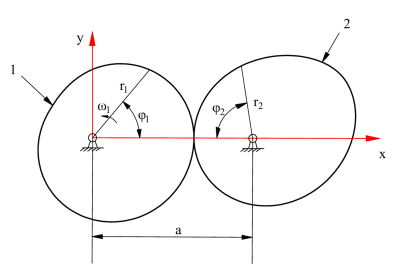
Fig. 7. Denatured Pascal limacon gear pair
2.5.1 Rotational Angle Relationship of the Denatured Pascal Limacon Gear
Since the denatured Pascal limacon gear has a non-circular shape, the angular relationship between the driving and driven gears can be obtained from Eq. (4), as shown in Fig. 8.
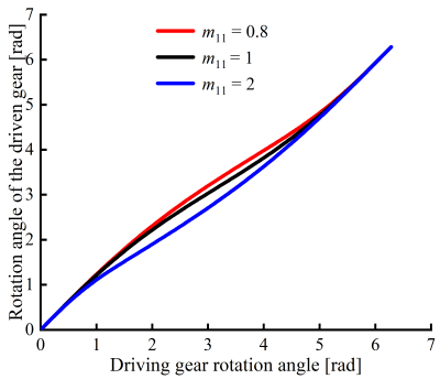
Fig. 8. Rotational angle relationship of the denatured Pascal limacon gea
Figure 8 illustrates the angular relationship curves of the driving and driven gears under different denaturation coefficients m11 = 0.8, 1, 2, revealing a clear nonlinear angular displacement mapping. A smaller m11 (e.g., 0.8) results in a larger angular displacement of the driven gear, indicating a higher transmission ratio and faster variation in angular velocity. In contrast, a larger m11 (e.g., 2) shows a slower change in the low-angle region and accelerated growth in the high-angle region, exhibiting a “slow-start and fast-return” transmission characteristic.
This variable-speed transmission characteristic is advantageous for optimizing the motion of the parallelogram four-bar onion planting mechanism. It ensures low-speed stability during the planting phase to enhance precision; during the reset phase, it enables high-speed return to improve operational efficiency. These features highlight the practical value of the denatured Pascal limacon gear in onion transplanting machines and other agricultural mechanization applications.
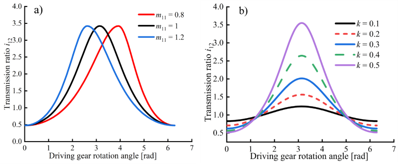
Fig. 9. Transmission ratios under different coefficient of denaturation and eccentricity
2.5.2 Gear ratio of the denatured Pascal limacon gear
To carry out optimal design, it is essential to first investigate the transmission ratio of the denatured Pascal limacon gear, as this establishes a theoretical basis that enables the optimization of the transplanting mechanism.
The concepts of eccentricity and relative center distance are introduced to aid in the analysis of the transmission characteristics of the denatured Pascal limacon gear. Let the ratio of the center distance a to l be defined as the relative center distance d:
d=\frac{a}{l}
\tag{11}
\end{equation}$$
The eccentricity of the denatured Pascal limacon gear is defined as the ratio of the generating circle diameter l to the developed length l, that is:
k=\frac{b}{l}
\tag{12}
\end{equation}$$
For a meshing pair of denatured Pascal limacon gears, under the assumption of negligible sliding and deformation, from the pitch curve in Eqs. (11) and (12), the transmission ratio is derived as follows:
i_{12}(\varphi_1)=
\frac{
a-r_1(\varphi_1)
}{
r_1(\varphi_1)
}
=
\left\{
\begin{aligned}
&\frac{
d-\left(k\cos(m_{11}\varphi_1)+1\right)
}{
k\cos(m_{11}\varphi_1)+1
},\\
&\frac{
d-\left(k\cos(m_{12}(2\pi-\varphi_1))+1\right)
}{
k\cos(m_{12}(2\pi-\varphi_1))+1
}.
\end{aligned}
\right.
\tag{13}
\end{equation}$$
The denaturation coefficient is a key parameter in the design of the denatured Pascal limacon gear, and different values of this coefficient will have a significant impact on the transmission ratio of the denatured Pascal limacon gear. The eccentricity directly reflects the non-circular characteristics of the pitch curve of the non-circular gear and plays an important role in the fluctuation range of its transmission ratio. Therefore, this paper adopts the method of controlling variables to study and analyze the influence of the denaturation coefficient and eccentricity on the transmission ratio of the denatured Pascal limacon gear.
When other design parameters are kept constant, selecting different denaturation coefficients, such as m11 = 0.8, m12 = 1.333; m11 = 1, m12 = 1 and m11 = 1.2, m12 = 0.857, yields the effect of the denaturation coefficient on the transmission ratio, as shown in the left part of Fig. 9. Similarly, under the same design conditions, choosing different eccentricities demonstrates the influence of eccentricity on the transmission ratio, as illustrated in the right part of Fig. 9.
As shown in Fig. 9a, the range of variation in the gear transmission ratio remains unchanged under different denaturation coefficients. However, the larger the denaturation coefficient, the smaller the driving gear rotation angle when the transmission ratio reaches its extreme values. This implies that the denaturation coefficient affects the time ratio between the working stroke and the return stroke during the transplanting process. Additionally, Fig. 9b shows that as the eccentricity increases, the variation range of the transmission ratio becomes larger. Therefore, selecting an appropriate eccentricity can significantly enhance transplanting efficiency.
2.5.3 Variation of Angular Velocity and Angular Acceleration of Denatured Pascal Limacon Gear
Based on the principles of gear transmission, the equations for the angular velocity and angular acceleration of the gear pair can be derived as follows:
Angular velocity of the gear pair:
\omega_2
=
\frac{\omega_1}{i_{12}}
=
\left\{
\begin{aligned}
&
\frac{
\omega_1\left(k\cos(m_{11}\varphi_1)+1\right)
}{
d-\left(k\cos(m_{11}\varphi_1)+1\right)
},
&&0\leq\varphi_1\leq\frac{\pi}{m_{11}},\\
&
\frac{
\omega_1\left(k\cos(m_{12}(2\pi-\varphi_1))+1\right)
}{
d-\left(k\cos(m_{12}(2\pi-\varphi_1))+1\right)
},
&&\frac{\pi}{m_{11}}\leq\varphi_1\leq2\pi.
\end{aligned}
\right.
\tag{14}
\end{equation}$$
Angular acceleration of the gear pair:
\begin{aligned}
\xi_2
&=
\frac{d\omega_2}{dt}
=
-\omega_1^2
\frac{
i_{12}'(\varphi_1)
}{
i_{12}^2(\varphi_1)
}\\
&=
\left\{
\begin{aligned}
&
-\frac{
\omega_1^2dkm_{11}\sin(m_{11}\varphi_1)
}{
\left(d-k\cos(m_{11}\varphi_1)-1\right)^2
},
&&0\leq\varphi_1\leq\frac{\pi}{m_{11}},\\
&
\frac{
\omega_1^2dkm_{12}\sin(m_{12}(2\pi-\varphi_1))
}{
\left(d-k\cos(m_{12}(2\pi-\varphi_1))-1\right)^2
},
&&\frac{\pi}{m_{11}}\leq\varphi_1\leq2\pi.
\end{aligned}
\right.
\end{aligned}
\tag{15}
\end{equation}$$
As shown in Fig. 10, during the continuous increase of the denaturation coefficient, similar to the transmission ratio, the variation ranges of the angular velocity and angular acceleration of the driven gear remain unchanged. This indicates that the denaturation coefficient does not affect the magnitude of the angular velocity and angular acceleration of the driven gear. However, within one rotation cycle of the gear, a larger denaturation coefficient results in the peak angular velocity of the driven gear occurring at a smaller rotation angle of the driving gear. Therefore, when studying the combined mechanism of the denatured Pascal limacon gear, it is important to select an appropriate denaturation coefficient to achieve optimization objectives.
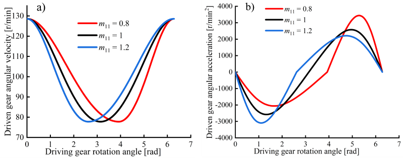
Fig. 10. Angular velocity and angular acceleration of the driven gear under different coefficient of denaturation
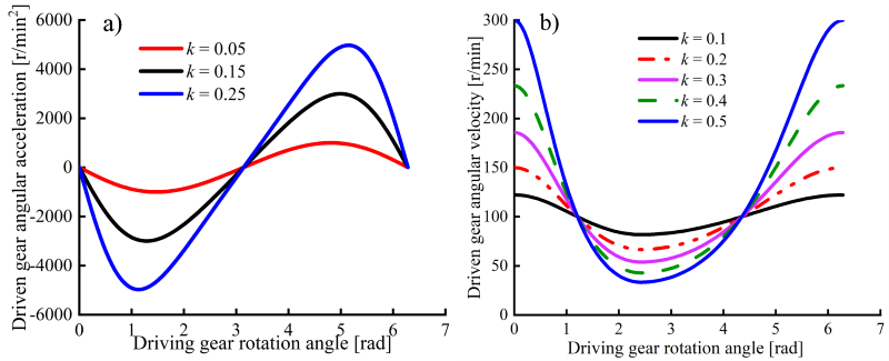
Fig. 11. Angular velocity and angular acceleration of the driven gear under different eccentricitie
As shown in Fig. 11, which illustrates the influence of eccentricity on angular velocity and angular acceleration, it can be observed that the greater the eccentricity, the driven gear exhibits a greater variation range in its angular velocity and angular acceleration. However, larger angular velocity and angular acceleration fluctuations introduce dynamic impacts, vibrations, and noise; these effects reduce transmission efficiency, shorten gear lifespan, and ultimately degrade the transplanting mechanism’s performance.
2.5.4 Influence of Input Speed on Transmission Characteristics
The input speed of the denatured Pascal limacon gear transmission mechanism is generally a constant value, and its magnitude directly affects the output working efficiency and rotational speed. As shown in Eq. (14), the input speed is directly proportional to the angular acceleration of the driven gear. Figure 12 shows the variation curves of the driven gear’s angular acceleration under different input speeds.
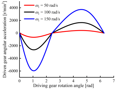
Fig. 12. Driven gear angular acceleration at different input speeds
Under the same denaturation coefficient and eccentricity, variations in input speed have a significant impact on angular acceleration. The higher the input speed, the greater the variation range of the driven gear’s angular acceleration, which greatly affects the dynamic stability of the mechanism.
2.6 Mathematical Models of Displacement, Velocity and Acceleration of the Planting Mechanism
As shown in Fig. 2b, let O2A = l1, AB = l2, BD = l3, O2D = l4, BC = l5, CE = l6. This mechanism is a parallelogram planting mechanism, hence l1 = l3, l2 = l4. The crank O2A is rigidly connected to the driven gear, meaning the crank rotates synchronously with the driven gear. The angle O1O2 between O2A and EF represents the initial phase angle of the crank. Therefore, the displacement equation of point O2A is:
\left\{
\begin{aligned}
&X_{O_2}=X_{O_1}+\left(l_{O_1O}+l_{OO_2}\right),\\
&Y_{O_2}=Y_{O_1}.
\end{aligned}
\right.
\tag{16}
\end{equation}$$
The displacement equation of point A is:
\left\{
\begin{aligned}
&X_A=X_{O_2}+l_1\cos(\alpha-\varphi_2),\\
&Y_A=Y_{O_2}-l_1\sin(\alpha-\varphi_2).
\end{aligned}
\right.
\tag{17}
\end{equation}$$
According to geometric relationships, the displacement equation of point E is:
\left\{
\begin{aligned}
&X_E=X_A+\left(l_2+l_3\right),\\
&Y_E=Y_A-l_6.
\end{aligned}
\right.
\tag{18}
\end{equation}$$
This study utilizes a computational software platform to perform dynamic simulations of the planting mechanism’s motion trajectories based on the established mathematical model. The code employs the platform’s integral function to calculate the pitch curve circumference and the fsolve solver to optimize the center distance parameter. Using a central difference scheme, the platform computes the first and second derivatives of Eq. (18), yielding the planting point’s velocity and acceleration curve from point E displacement coordinates. These derived kinematic parameters are then used to simulate and analyze the mechanism’s dynamic behavior and motion trajectory.
2.7 Factors Influencing the Kinematic Characteristics of the Planting Mechanism Driven by Denatured Pascal Limacon Gear
The performance of the planting mechanism is mainly reflected in three aspects: planting trajectory, planting speed and acceleration. Among them, the planting trajectory has a direct impact on the efficiency and planting effect of the planting mechanism. The planting speed affects the uprightness of the transplanted seedlings after transplantation. The planting point acceleration has a significant influence on the wear degree of the planting device. Based on the agronomic requirements for onion transplanting: plant spacing of 150 mm to 300 mm, planting depth of 20 mm to 30 mm, and plant height of 150 mm to 200 mm, the forward speed of the machine is set to 300 mm/s, and the height of the duckbill planter is set to l6 = 230 mm. According to the design requirements and constraints of the planting mechanism, a set of initial values is selected: l1 = l3 = 40, l2 = l4 = 180, l5 = 90, l6 = 230, b = 5, l = 40, m11 = 1, and the initial installation angle of the crank α = 0. Using the computational software platform and applying the control variable method for single-factor analysis, three equally spaced values were selected for each parameter. The corresponding transplanting trajectories and vertical velocity–time curves for point E were then obtained, as shown in the Figs.
2.7.1 The Influence of Each Parameter on the Planting Trajectory
As depicted in Fig. 13a, increasing the gear center distance a does not alter the vertical displacement range of the planting point, but the horizontal trajectory translates posteriorly while maintaining constant row spacing. The lateral deviation of the duckbill planter after entering the soil changes only slightly, resulting in a small variation in planting depth. When a = 40 mm, the planting depth is 45 mm; when a = 80 mm, the planting depth is 26 mm; and when a = 1200 mm, the planting depth is 19 mm. Therefore, as the center distance increases, the planting depth shows a decreasing trend.
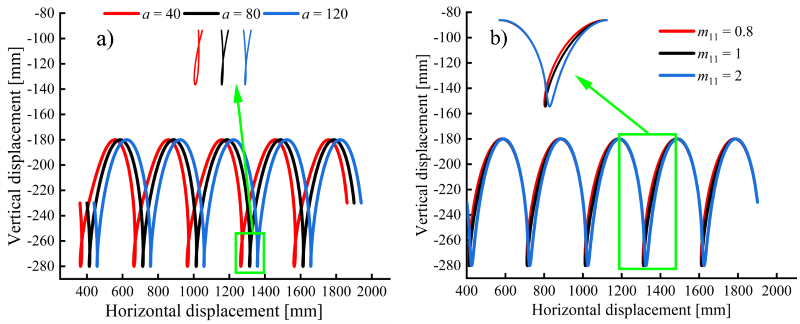
Fig. 13. The growth trajectory varies with: a) the center distance, and b) the denaturation coefficient
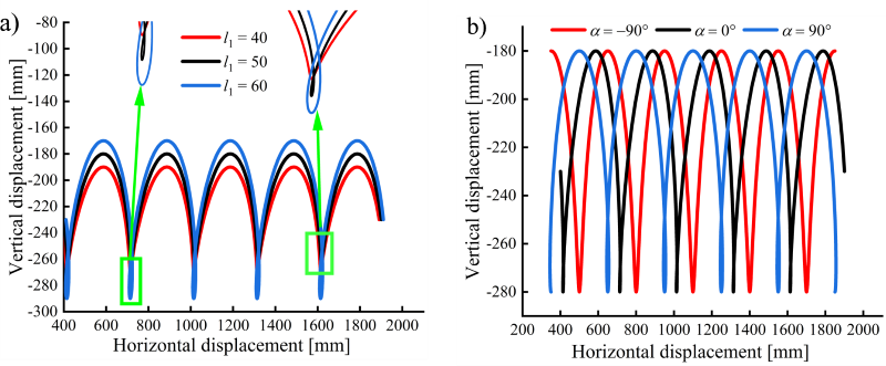
Fig. 14. The growth trajectory varies with: a) the length of crank, and b) the initial phase angle of crank
As shown in Fig. 13b, although the vertical trajectory range remains unchanged with the increase of the gear denaturation coefficient m11, the planting depth varies significantly. When m11 = 0.8, the planting depth is 30 mm; when m11 = 2, the planting depth reaches 2 mm. Therefore, the denaturation coefficient should not be too large when designing the driving gear.
As shown in Fig. 14a, with the increase of l1, the planting point trajectory becomes vertically stretched, resulting in a larger offset in the soil-entry segment. Meanwhile, the overlapping portion of the curve during planting also extends, leading to an increase in planting depth. Similarly, Fig. 14b shows that although changes in the initial installation angle of crank AB do not affect the planting spacing, they have a significant impact on the planting depth and trajectory. Therefore, the planting depth can be optimized by adjusting the initial installation angle.
As shown by the unit’s forward speed and the trajectory in Fig. 15, the speed mainly affects the planting rhythm and spacing, with no significant impact on planting depth. Therefore, the forward speed of the unit can be reasonably adjusted by investigating the optimal plant spacing for onion planting.
2.7.2 Influence of Various Parameters on the Horizontal Velocity Component of the Planting Point
As shown in Fig. 16a, the variation in center distance does not significantly affect the motion period or frequency. However, a larger center distance results in a smoother horizontal motion of the planting point, enhancing the effectiveness of “zero-velocity planting.” Analysis of Fig. 16b reveals that as the gear denaturation coefficient increases, for example, when m11 = 2, the ascending segment becomes steeper while the descending segment becomes more gradual, exhibiting pronounced asymmetry and nonlinearity. This enhances the asymmetry of the mechanism. The gear denaturation coefficient is thus a key parameter influencing the amplitude and stability of the horizontal motion in the planting mechanism. Its selection should be carefully balanced based on the onion planting environment and performance requirements.
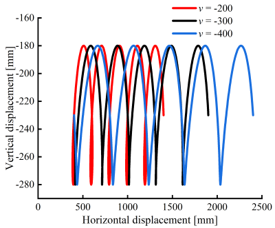
Fig. 15. The curve of the planting trajectory changes with the variation of the machine’s forward speed
As shown in Fig. 17a, with the increase in the length of crank AB, both the upper and lower bounds of the horizontal velocity of the planting point increase, indicating more intense reciprocating motion of the mechanism. This suggests that crank length has a significant impact on the motion amplitude. When L1 = 60 mm, the velocity fluctuation is the strongest, implying that the driving force of the unit is the greatest at this length. However, this may also lead to larger impacts and vibrations. Analysis of Fig. 17b shows that the installation angle of the crank mainly affects the phase characteristics of the velocity curve. As the angle α changes from negative to positive, the velocity peak gradually shifts backward, indicating that the initial installation angle can be used to adjust the planting position during the planting operation.
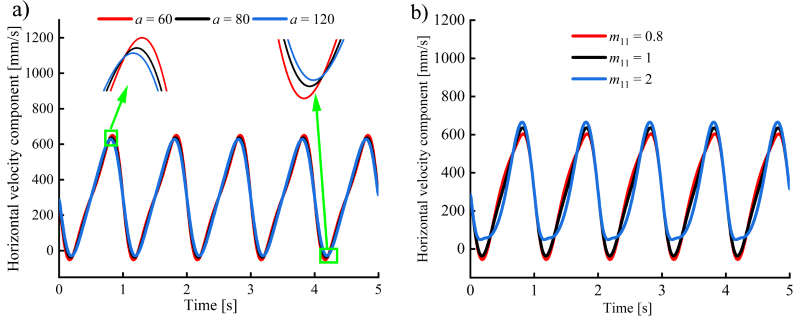
Fig. 16. The horizontal velocity varies with: a) the center distance, and b) the denaturation coefficient
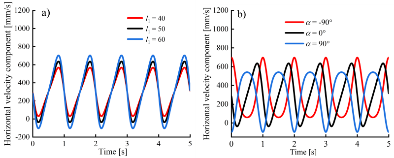
Fig. 17. The horizontal velocity varies with: a) the length of crank, and b) the initial phase angle of crank
As shown in Fig. 18, with the increase in the unit’s forward speed, the horizontal velocity fluctuation range of the planting point expands significantly – the peak velocity rises from approximately 500 mm/s to 700 mm/s.
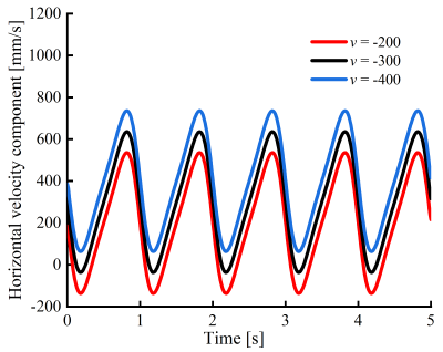
Fig. 18. The horizontal velocity curve changes along with the variation of the machine’s forward speed
This indicates a velocity coupling effect between the tractor forward velocity and the planter tip velocity. Therefore, selecting an appropriate forward speed is crucial to maintaining smooth motion and avoiding excessive dynamic loads, especially in precision-demanding tasks like onion transplanting, where velocity stability directly affects planting accuracy and depth control.This indicates a velocity coupling effect between the tractor forward velocity and the planter tip velocity. Therefore, selecting an appropriate forward speed is crucial to maintaining smooth motion and avoiding excessive dynamic loads, especially in precision-demanding tasks like onion transplanting, where velocity stability directly affects planting accuracy and depth control.
3 CASE STUDY ON PARAMETER OPTIMIZATION
3.1 Genetic Algorithm Optimization
3.1.1 Mathematical Modeling
To achieve zero-velocity transplanting and stable planting depth, a multi-objective optimization model is formulated based on the established kinematic model of the transplanting mechanism. The horizontal velocity at seedling release Vx, planting depth H, and the pickup trajectory range Y are selected as objective functions, while planting depth requirements and variable bounds are imposed as constraints. Eight key geometric parameters of the transplanting mechanism m11, l, l1, l2, l5, l6, α and b identified through preliminary screening are treated as design variables. Accordingly, the following multi-objective optimization mathematical model is established:
Optimization variable: X = [m11, l, l1, l2, l5, l6, α, b]T.
Objective function: {f1(X)=|Vx(te)|, f2(X)=|H–25|, f3(X)=|Y(X–300}.
The mathematical expression for the optimization problem is:
Minimize F(X) = [f1(X), f2(X), f3(X)]T.
Subject to 25 ≤ H ≤ 30, Xmin ≤ X ≤ Xmax.
In the model, Vx(te) denotes the horizontal velocity component of point E at the planting instant te, which corresponds to the lowest point of the trajectory. The planting depth H is defined as the vertical displacement range in the vicinity of the trajectory minimum (|XE – XE(tE)| ≤ 0.5 mm). The parameter Y(X) = max(YE) – min(YE) represents the displacement range in the vertical direction. Xmax and Xmin denote the upper and lower bounds of each design variable, respectively.
3.1.2 Multi-Objective Optimization Based on NSGA-II
NSGA-II is a classical multi-objective optimization algorithm proposed by Deb et al. [31]. By employing non-dominated sorting and a crowding-distance comparison mechanism, the algorithm effectively preserves population diversity and converges toward a well-distributed set of optimal solutions that closely approximate the true Pareto front.
The population size is set to 100, and the maximum number of generations is 200. The crossover probability is 0.8, with a crossover distribution index of 10, while the mutation distribution index is set to 20.
3.1.3 Optimized Results
The NSGA-II optimization process yielded a set of optimal parameters, as follows: m11 = 1.5, b = 13 mm, l = 53 mm, l1 = 82 mm, l2 = 254 mm, l5 = 61 mm, l6 = 119 mm, and α = 6°.
Based on the optimized mechanism parameters, the key design parameters for the denatured Pascal limacon gear pair were derived, as listed in Table 2 and in Eq. (19). This provides the necessary theoretical basis for subsequent numerical simulations.
Table 2. Design parameters of the denatured Pascal limacon gear pair
| Basic Parameters | Value |
|---|---|
| Modulus [mm] | 2 |
| Tooth number | 55 |
| Center distance [mm] | 110 |
| Tooth width [mm] | 30 |
| Pressure angle [°] | 20 |
| Tooth addendum [mm] | 2 |
| Tooth dedendum [mm] | 1.5 |
| Whole depth [mm] | 4.5 |
| Pitch curve | Eq. (19) |
Pitch curve equation:
r_1(\varphi_1)=
\left\{
\begin{aligned}
&13\cos(1.5\varphi_1)+53,
&&0\leq\varphi_1\leq\frac{2\pi}{3},\\
&13\cos\!\left(0.375(2\pi-\varphi_1)\right)+53,
&&\frac{2\pi}{3}\leq\varphi_1\leq2\pi.
\end{aligned}
\right.
\tag{19}
\end{equation}$$
3.2 Theoretical Model Validation Based on Kinetic Simulation
To validate the accuracy of the theoretical model and optimization results, this study employed a multibody dynamics simulation method to establish a virtual prototype of the planting mechanism. The optimized parameters were imported into the simulation environment. After appropriately simplifying components and correctly defining kinematic pairs and drives, the motion trajectory, horizontal velocity, and vertical velocity data at the planting point were extracted. Based on this, quantitative comparative analysis was conducted between the theoretical curve and the simulation curve by calculating the relative error at corresponding data points.
Definition of relative error:
e_{\mathrm{rel}}
=
\left|
\frac{y_{\mathrm{sim}}-y_{\mathrm{theory}}}
{y_{\mathrm{theory}}}
\right|
\times 100\%.
\tag{20}
\end{equation}$$
The results show that the average relative error between the two models is less than 4 %. This indicates good consistency between the simulation model and the theoretical model, providing reliable predictions for subsequent physical experiments on planting mechanisms.
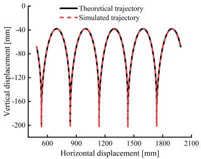
Fig. 19. Comparison of end-effector trajectories
As shown in Fig. 19, the comparison between simulation results and theoretical model calculations demonstrates high alignment in motion trajectories. The planting point vertical height of 163 mm, plant spacing of 300 mm, and planting depth of 27 mm all meet the preset agronomic requirements.
Simultaneously, the velocity characteristics of the end-effector of the planting mechanism were analyzed, yielding the horizontal and vertical velocity variation curves shown in Figs. 20 and 21. Consistent with the trajectory analysis results, the simulation curves generally align well with the theoretical curves, exhibiting only minor discrepancies as shown in Fig. 20 due to inherent numerical fluctuations in multibody dynamics simulations.
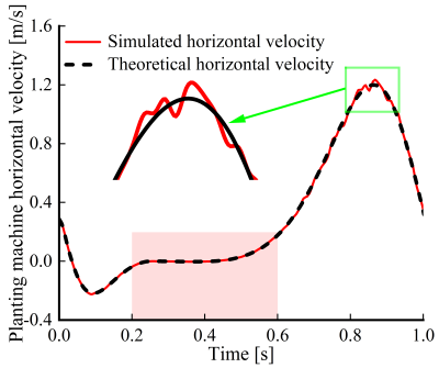
Fig. 20. Comparison of end-effector horizontal velocities
The horizontal velocity curve indicates that during the planting phase (t is 0.2 s to 0.6s), the planter’s horizontal velocity approaches zero, achieving “zero-speed transplanting” that helps maintain the seedlings’ upright posture. In the vertical velocity curve, point a corresponds to the planter reaching the seedling pickup position, while point b corresponds to the planter reaching the planting position, where the vertical velocity is zero, ensuring stable planting operations. Additionally, the curves reveal that the vertical velocity during the return phase is significantly higher than during the seedling delivery phase, reflecting the “slow planting, fast return” characteristic that enhances operational efficiency.
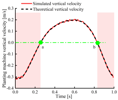
Fig. 21. Comparison of end-effector vertical velocities
4 CONCLUSIONS
In response to issues such as unreasonable end-effector trajectories and insufficient mechanical stability in the mechanized transplanting of onions, this study proposes a parallelogram-type onion transplanting mechanism driven by a denatured Pascal limacon gear. The transmission and kinematic characteristics of the mechanism are thoroughly analyzed and optimized. Key research findings are summarized as follows:
- A novel onion transplanting mechanism driven by a denatured Pascal limacon gear was designed. Its working principle was systematically elucidated, transmission characteristics of the non-circular gear were analyzed using kinematic mapping, and the mathematical model of the mechanism was derived.
- Based on the mathematical model of the mechanism, the influence of parameters such as the gear denaturation coefficient, crank length, initial installation angle, and forward speed of the unit on the trajectory and velocity of the planting point was investigated using the computational software platform.
- A multi-objective optimization of the key parameters of the planting mechanism was conducted using a genetic algorithm. A comparative analysis of the optimized theoretical results and simulation outcomes reveals that the theoretical model recommends a planting depth of 27 mm and a spacing of 300 mm. Furthermore, the horizontal separation velocity approaches zero during the seedling planting phase, fully meeting the optimized agronomic requirements. Furthermore, by calculating the relative error between valid data points on the theoretical and simulated curves, an average error of less than 4 % was obtained, validating the reliability of the optimized model. This result provides credible simulation support for subsequent physical prototype experiments.
References
- Wang, X. High-yield and high-efficiency cultivation techniques for onion seedling transplanting. Agric Sci Technol Inf 144 32-34 (2022) DOI:10.15979/j.cnki.cn62-1057/s.2022.14.006.
- Elhami, B., Ghasemi Nejad Raini, M., Taki, M., Marzban, A., Heidarisoltanabadi, M. Analysis and comparison of energy-economic-environmental cycle in two cultivation methods (seeding and transplanting) for onion production (case study: central parts of Iran). Renew Ener 178 875-890 (2021) DOI:10.1016/j.renene.2021.06.117.
- Pandirwar, A., Kumar, A., Mani, I., Islam, S. Biometric properties of onion seedlings relevant to the development of onion seedling transplanter. J Appl Natur Sci 7 768-773 (2015) DOI:10.31018/jans.v7i2.681.
- Ye, B., Zeng, G., Deng, B., Yang, C., Liu, J., Yu, G. Design and tests of a rotary plug seedling pick-up mechanism for vegetable automatic transplanter. Int J Agric Biol Eng 13 70-78 (2021) DOI:10.25165/j.ijabe.20201303.5647.
- Nandede, B., Carpenter, G., Byale, N., Chilur, R., Jadhav, M.L., Pagare, V. Manually operated single row vegetable transplanter for vegetable seedlings. Int J Agric Sci 9 4911-4914 (2017).
- Stubbs, S., Colton, J. The design of a mechanized onion transplanter for bangladesh with functional testing. Agriculture 12 1790-1790 (2022) DOI:10.3390/agriculture12111790.
- Reza, M.N., Islam, M.N., Chowdhury, M., Ali, M., Islam, S., Kiraga, S. et al. Kinematic analysis of a gear-driven rotary planting mechanism for a six-row self-propelled onion transplanter. Machines 9 183-183 (2021) DOI:10.3390/machines9090183.
- Habineza, E., Reza, M.N., Bicamumakuba, E., Haque, M.A., Park, S.-H., Lee, D.-H. et al. Pepper transplanting mechanisms and kinematic simulation analysis: A review. Precis Agric 6 18 (2024) DOI:10.12972/pastj.20240002.
- Yin, D., Zhang, N., Zhou, M., et al. Optimal design and experiment of high speed duckbill planting mechanism with variable catch-seedling attitude. Trans Chin Soc Agric Mach 51 65-72 (2020).
- Rasool, K., Ali, M., Chowdhury, M., Kwon, H.J., Swe, K.M., Chung, S.O. Theoretical analysis of velocity, acceleration and torque calculation of a five-bar onion transplanting mechanism. IOP Conf Ser: Earth Environ Sci 733 012019 (2021) DOI:10.1088/1755-1315/733/1/012019.
- Sharma, A., Khar, S. Design and development of a vegetable plug seedling transplanting mechanism for a semi-automatic transplanter. Sci Hortic 326 112773 (2024) DOI:10.1016/j.scienta.2023.112773.
- Wu, X., Wang, G. Non-Circular Gears and Non-Uniform Ratio Drives, China Machine Press, Beijing (1997).
- Xu, X., Zhou, M., Chen, X., Yang, J. Processing method of gearbox with non-circular gear train and its application in rice potted seedling transplanting mechanism. Agriculture 12 1676 (2022) DOI:10.3390/agriculture12101676.
- Ye, B., Yi, W., Yu, G., Yang, G., Xiong, Z. Optimization design and test of rice plug seedling transplanting mechanism of planetary gear train with incomplete eccentric circular gear and non-circular gears. Int J Agric Biol Eng 10 43-55 (2017) DOI:10.25165/j.ijabe.20171006.2712.
- Zhao, X., Ye, J., Chu, M., Dai, L., Chen, J. Automatic scallion seedling feeding mechanism with an asymmetrical high-order transmission gear train. Chin J Mech Eng 33 4690-4694 (2020) DOI:10.1186/s10033-020-0432-9.
- Shi, L., Zhao, W., Sun, B., Dai, F., Xin, S., Sun, W., et al. Design and experiment of a non-circular gear-driven corn direct-seeding hole planter. J Agric Mech 55 157-167 (2024).
- Xu, H., Wang, L., Miao, Y., Sun, L. Kinematic synthesis and optimization design of a rice pot seedling transplanting mechanism. Proc Inst Mech Eng C-J Mech Eng Sci 238 1366-1381 (2024) DOI:10.1177/09544062231184804.
- Yu, Y., Liu, J., Ye, B., Yu, G., Jin, X., Sun, L. et al. Design and experimental research on seedling pick-up mechanism of planetary gear train with combined non-circular gear transmission. Chin J Mech Eng 32 49 (2019) DOI:10.1186/s10033-019-0357-3.
- Xin, J., Kaixuan, Z., Jiangtao, J., Hao, M., Jing, P., Zhaomei, Q. Design and experiment of automatic transplanting device for potted tomato seedlings. Proc Inst Mech Eng C-J Mech Eng Sci 233 1045-1054 (2019) DOI:10.1177/0954406218762954.
- Liu, C. Design and Experiment of a Reciprocating Duckbill-Type Transplanting Device. Chinese Academy of Agricultural Mechanization Sciences, Beijing (2023).
- Song, W., He, Y., Zhou, Y. Design and extraction of tooth profile of denatured elliptical gear. Adv Mech Eng 14 (2022) DOI:10.1177/16878132221144544.
- Liu, Y., Lu, S., Xu, J., Yang, S., Tao, W. Design of piecewise deformed elliptical gear with closed pitch curve and its conjugate pair. Sci Rep 12 17156 (2022) DOI:10.1038/S41598-022-22139-7.
- Fang, M.H. The application and parameter optimization of Pascal curve gear in the transplanting mechanism. Appl Mech Mater 1968 446-449 (2012) DOI:10.4028/www.scientific.net/AMM.201-202.446.
- Cha, T., Bang, J., Lee, J.S., Lee, S.G., Choi, J.H. Optimization of the macro-geometry of planetary gears using multibody dynamics and genetic algorithm. J Mech Sci Technol 39 2375-2391 (2025) DOI:10.1007/S12206-025-2204-Z.
- Zhao, X., Zhang, X., et al. Design and experimental research on a new hybrid-driven flowerpot mechanism. Appl Eng Technol 40 82 (2020).
- Zeng, G., Chen, J., Xia, X., et al. Design and experiment of a pull-type carrot harvester driven by non-circular gears. Chin J Agric Mech 46 6-10 (2025).
- Liu, D., Ren, T. Study on deformed limacon gear and motion optimization of its serial mechanism. J Mech Des 133 061004 (2011) DOI:10.1115/1.4004116.
- Liu, Y., Lu, S., Xu, J., Yang, S., Tao, W. Design of piecewise deformed elliptical gear with closed pitch limacon and its conjugate pair. Sci Rep 12 17156 (2022) DOI:10.1038/S41598-022-22139-7.
- Zhao, H., Chen, J., Xu, G., et al. Design and analysis of high-order multi-stage modified Pascal worm gears. Mech Des Manuf 250 242-246 (2024).
- Zhao, H., Chen, J., Xu, G. Advanced design strategies and applications for enhanced higher-order multisegment denatured pascal limacon gears. J Vibroeng 27 39-57 (2025) DOI:10.21595/JVE.2024.24255.
- Deb, K., Pratap, A., Agarwal, S., Meyarivan, T. A fast and elitist multiobjective genetic algorithm: NSGA-II. IEEE Trans Evol Comput 6 182-197 (2002) DOI:10.1109/4235.996017.