

1 INTRODUCTION
With the continuous development of high-performance grinding machines and growing maturity of high-speed grinding theory, the high-speed wheel linear grinding of camshafts has become an inevitable technological trend [1,2]. Notably, the dynamic excitation forces within the abrasive processing system exhibit a nonlinear escalation in response to elevated grinding wheel peripheral velocities, attributable to centrifugal loading effects and amplified aerodynamic interactions at the tool-workpiece interface [3,4]. During the dynamic engagement between the rotary abrasive element and the workpiece surface, the machining assembly exhibits elastic displacements subjected to combined influence of orthogonal process loads and non-collinear excitations. This phenomenon induces measurable deviations between programmed grinding depth and actual cutting penetration, subsequently altering the effective contact trajectory and modulating workpiece detachment mechanisms within the active tribological zone [5,6]. When the retraction displacement value exceeds the allowable value for stable high-speed, the surface waviness of the camshaft high-speed grinding deteriorates significantly, and in severe cases, the grinding wheel or workpiece may be damaged, leading to processing failure [7-10].
In view of the critical influence of elastic deformation on grinding performance and surface quality, numerous researchers have carried out extensive research on elastic deformation. Pereverzev et al. [11] established a grinding force model for internal grinding by analyzing the elastic deformation and motion geometry of the processing system, thereby revealing how the system’s structural compliance affects abrasive process loads and surface topography irregularities. Nosenko et al. [12] conducted integrated analytical and empirical investigations of face grinding on annular bearing components, incorporating both the electromagnetic characteristics of the workholding apparatus and examining how normal force components influence workpiece structural compliance behavior. Yamada et al. [13] reported that the degree of elastic deformation of the grinding wheel depends strongly on the stiffness of the process system, highlighting the close coupling between elastic deformation and system stiffness variations. Wei et al. [7] employed the grinding geometry to calculate the moving contact arc length and grinding forces during the thread grinding process and subsequently established an elastic deformation model for the processing apparatus. Mueller et al. [14] studied the elastic deformation behavior of the processing system during fiber-reinforced ceramic grinding, analyzing the influence of system elastic deformation on the quality of ceramic surface waviness. Furthermore, Yin et al. [15] developed the surface waviness formation models in which wheel spindle vibrations and non-uniform wheel topography were identified as primary sources of waviness.
The elastic deformation of the grinding system is affected primarily by two significant factors, namely the dynamic stiffness and dynamic grinding forces during grinding process [16,17]. Oiwa et al. [18] measured working profile, support stiffness, and grinding forces during operation, and researched how stiffness affects the milled profile. Albertelli et al. [19] emphasized the significance of evaluating the dynamic characteristics of the entire machine, and proposed using the average maneuverability within the frequency range of interest as a key index of dynamic performance. Uriarte et al. [20] constructed the machine-tool stiffness chain and experimentally verified the static stiffness of key components, including the cutting tool. Shen et al. [21] analyzed the elastic deformation during crankshaft grinding process and concluded that the grinding forces, clamping forces and self-weight of the process system are the primary contributors to deformation. They also designed an auxiliary mechanism to reduce the deformation of the system, improve the stability of the process, and improve surface waviness. Based on the steadiness theory of the regenerative chatter model, the steadiness of the crankshaft grinder was analyzed by Cha et al. [22] to automatically identify the stable and chatter prone regions. Liu et al. [17] incorporated elastic deformation into the non-circular grinding process to calculate dynamic grinding depth and derived a dynamic grinding force model capable of predicting grinding stability. Li et al. [23] used modal analysis with excitation technology to study and successfully extract the dynamic vibration parameters of the machine tool. Kareepadath Santhosh et al. [24] conducted a comparative investigation of cooling-lubrication methods in cemented carbide pin grinding using vitrified diamond tools, and demonstrated that LCO₂-MQL significantly reduces grinding forces and specific energy despite exacerbating wheel loading. Robles-Ocampo et al. [25] developed a nonlinear dynamic model for centerless grinding process by representing workpiece lobing as polygonal geometry and incorporating the geometric stability index, and demonstrated that the system exhibits duffing-type stiffness characteristics with a critical lobing order of N = 39 triggering instability. A non-contact excitation approach for assessing the dynamic stiffness of a rotating spindle was proposed by Matsubara et al. [26], who studied the dynamic indeterminacy and its influence on cutting stability. Xia et al. [27] developed a novel toolholder featuring high dynamic stiffness to enhance the chatter stability. Despite these advances, investigations on elastic deformation mechanisms in the high-speed grinding process, such as camshafts, remain limited.
Therefore, this study fully considers the specific characteristics of the high-speed camshaft grinding process and conducts an in-depth investigation into the elastic deformation of the grinding system. The research focuses on three main aspects. First, the geometric kinematics of constant-linear-speed camshaft grinding are analyzed, and a correlation is established between the feed displacement of the high-speed grinding wheel frame and the camshaft contour rotation angle. Second, an experimental platform for high-speed camshaft grinding is constructed to evaluate the dynamic stiffness, elastic deformation, and grinding forces of the process system. Third, the relationships among dynamic stiffness, grinding force, and elastic deformation under varying process parameters are examined, along with an analysis on how the number of grinding cycles influences the grinding wheel’s elastic retreat in high-speed camshaft grinding.
2 METHODS AND MATERIALS
2.1 Geometry Kinematics Analysis Based on Constant Line Speed Grinding
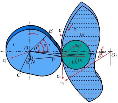
The corresponding relationship between the real-time feed displacement of the grinding wheel and the camshaft rotational angle is a critical factor for analyzing elastic deformation during the high-speed camshaft grinding. Constant-linear-speed grinding is one of the most commonly used methods for camshaft machining [20,28], and this paper focuses its geometric kinematics. The cam profile is generated through the coupled motion of the X-axis and C-axis, as illustrated in the two-axis linkage grinding schematic in Fig. 1.
In Figure 1, position 1 indicates the camshaft workpiece, 2 the grinding wheel, and 3 the roller probe used for cam profile measurement, which remains tangent to the grinding point P. Point O is the center of the camshaft base circle, OB = rj representing the radius of the cam base circle, O1 is the center of the roller probe, whose radius is rg, the central point of the grinding wheel’s rotation axis is represented by O2, rs is the radius of the grinding wheel, θ is the rotation angle of the center of the cam relative to the center of the roller probe, α is the rotation angle of the center of the cam with respect to the center of the grinding wheel. The angle of rotation of the cam center relative to the grinding point P is denoted by β. The symbol ρ represents the instantaneous curvature radius, vs is the grinding wheel linear velocity, vj is the tangential velocity of the cam center with respect to the grinding point P, and vp is the grinding point velocity.
The feed displacement equation X(θ) of the grinding wheel can be expressed as:
From Equations (2) and (3), the cam profile angle α and the frame feed displacement X can be obtained, providing the theoretical basis for the study of elastic deformation in high-speed camshaft grinding. Let s(β) denote the grinding path of the grinding wheel. At a given moment, the grinding wheel is located at grinding point P, and after a time interval Δt, it moves to point P‘. The moving distance ds of the grinding wheel during this motion can be expressed as:
At this point, the speed of grinding point can be expressed as:
Assuming that the angular velocity at the base circle of the camshaft is ωj, then:
The angular velocity ω of the grinding point can be expressed as:
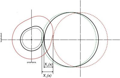
The displacement X and the cam angle α correspond one-to-one in time. Thus, for each discrete value of the cam angle α, the corresponding feed displacement X of the grinding wheel frame can be determined, yielding the complete displacement profile over one full revolution of the cam. The idle-feed displacement X1(α) and actual grinding-feed displacement X2(α) under the elastic deformation phenomenon can be obtained. The elastic deformation displacement e(α) under a given set of grinding process parameters is then calculated using Eq. (8).
2.2 Elastic Deformation and Dynamic Stiffness of the Grinding Process System
The dynamic characteristics of a grinding machine, particularly its stiffness, are strongly influenced by design and manufacturing imperfections [29,30]. In high-speed camshaft grinding, additional factors such as non-uniform hardness of the camshaft, uneven feed of the grinding wheel within a single rotation, and imbalance in the grinding wheel spindle further affect the system’s dynamic stiffness. These factors lead to elastic deformation, altering the shape and size of the grinding contact zone. As a result, the actual grinding penetration fails to reach the preset value, leading to grinding depth deviations and reduced machining accuracy [31].
According to the reference [17], the grinding depth actually achieved during the process can be expressed by Eq. (9):
where, a0 denotes the preset theoretical grinding depth, ks the dynamic stiffness of the processing apparatus, and kw is the grinding stiffness of the associated with the interaction between the grinding wheel and the workpiece. For a given machining system and grinding strategy, kw remains constant and is determined by the selected grinding process plan, the material properties of the grinding wheel, and the shape of the cam profile.
The processability of the machine tool is fundamentally governed by its dynamic performance, which directly affects machining quality, machining efficiency, and service life of the machine tool. Dynamic stiffness is an inherent structural attribute, determined entirely by machine’s mechanical configuration and assembly characteristics [19,33]. Dynamic stiffness reflects how the structure responds to the excitation frequency. It is defined as the ratio between the response acceleration spectrum and the excitation force spectrum measured between designated excitation and response points. The resulting response reflects the dynamic compliance at that location, with dynamic stiffness being inversely proportional to dynamic flexibility.
where, KD denotes the dynamic stiffness at the measurement point, and HIp represents the frequency response function of the process system. The excitation force applied at the excitation point is denoted as F(ω), while X(ω) denotes the corresponding acceleration response function at the acquisition point. The stiffness of the grinding process system serves as a key indicator of its resistance to deformation and its overall operational stability. This can be quantitatively evaluated using the following formula.
where, K is the overall stiffness of the grinding process system; K1, K2, …, Kn are the dynamic stiffness values of the key components of the process system.
2.3 Experimental
2.3.1 Experimental Scheme
The camshaft high-speed grinding elastic deformation experiments primarily consist of two major parts: (1) stiffness testing of the grinding system, and (2) measurement of elastic deformation displacement and grinding force during high-speed camshaft grinding. The experiment was conducted in three phases:
1. Experimental preparation and equipment setup: Trial grinding was performed to calibrate sensor sensitivity and accuracy, configure sampling frequencies, and set signal-processing parameters. External vibrations were monitored and isolated to minimize interference.
2. Grinding machine idling stage: With no load applied, feed-displacement and vibration-acceleration signals were collected under different process parameter settings. The dominant excitation frequencies of the system were identified, providing a baseline for comparison with subsequent tests.
3. High-speed grinding deformation testing: Grinding forces were measured using a dynamometer, and spindle vibration was recorded by an eddy-current displacement sensor. This data was used to calculate the system’s dynamic stiffness. Single-pass grinding tests under varying parameters captured real-time feed and force variations, while additional multi-pass tests evaluated how repeated grinding reduces elastic deformation.
The idling test was conducted to serve as a reference for the camshaft high-speed grinding elastic deformation experiments. Its purpose was to eliminate displacement deviations caused by the servo-system accuracy limitations and the inherent processing capacity of the grinding machine. By doing so, the feed displacement of the grinding wheel could be measured without the influence of elastic deformation. The process parameters used in the idling experiments are listed in Table 1.
Table 1. The experimental parameters of idling test of elastic deformation
|
Group |
Factors |
Feeding speed [mm/min] |
||
|---|---|---|---|---|
|
Grinding speed [m/s] |
Workpiece speed [1/min] |
Grinding depth [mm] |
||
|
1 |
90 |
90 |
0.01 |
4500 |
|
2 |
110 |
120 |
0.02 |
4500 |
|
3 |
130 |
150 |
0.03 |
4500 |
|
4 |
150 |
180 |
0.04 |
4500 |
2.3.2 Experimental Conditions
The camshaft high-speed grinding elastic deformation experimental platform, shown in Fig. 3, was composed of an ultra-high-speed camshaft composite grinding machine, a laser displacement sensor, a grinding force measurement system, a dynamic stiffness testing system, an eddy current sensor, a piezoelectric acceleration sensor, signal transmission lines, and a data acquisition and analysis system.
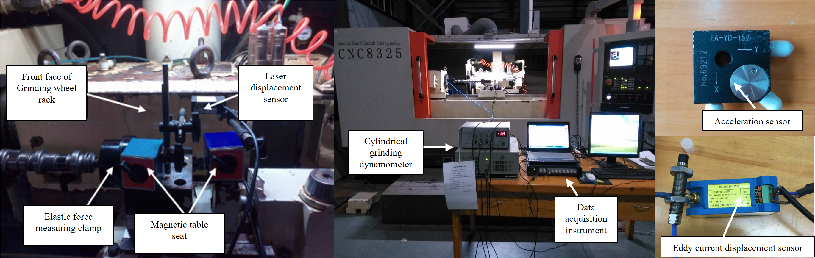
Table 2. Vitrified bonded CBN wheel parameters
|
Abrasive materials |
Bond |
Diameter of grinding wheel |
Wheel width |
Maximum speed |
Grain size |
Concentration |
Abrasive layer thickness |
|---|---|---|---|---|---|---|---|
|
CBN |
Vitrified |
400 mm |
25 mm |
200 m/s |
120# |
125 % |
20 mm |
The CNC8325 CNC camshaft compound grinding machine supports a maximum grinding wheel linear speed of 200 m/s and a maximum workpiece spindle speed of 240 1/min. A 3A1 high-speed vitrified bonded CBN grinding wheel is used, enabling stable grinding at speeds up to 200 m/s. The detailed specifications are listed in Table 2.
The experiment uses the SDC-CG2 series of external grinding dynamometer system, capable of measuring grinding forces in both the Y (radial) and Z (tangential) directions. During testing, the sampling frequency is set to 60 Hz. A dynamic signal testing module is employed for data acquisition, while its analysis module processes and analyzes the collected data. The CD33-30NV laser displacement sensor is used to measure the elastic deformation displacement of the camshaft during high-speed grinding. The laser displacement sensor uses a red semiconductor laser source with a wavelength of 655 nm and a maximum output power of 1 mW. It operates with a sampling period of 500 μs and a resolution of 0.01 μm.
3 RESULTS AND DISCUSSION
3.1 The Dynamic Stiffness of the Grinding Process System
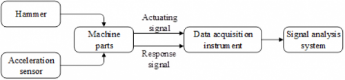
During the dynamic stiffness testing of the processing system, an impact hammer was used for initial excitation. A force sensor captured the excitation signal, while an acceleration sensor measured the corresponding response signal. By analyzing these signals, the frequency response functions of each key component were obtained, enabling the calculation of their dynamic stiffness. Based on the stiffness of each component, the overall dynamic stiffness of the system was then determined. The experimental setup is shown in Fig. 4.
To ensure the accuracy of component stiffness measurements in the process system, a dynamic stiffness pre-test was first conducted. Several excitation points were initially selected, and their frequency response functions were measured. Based on the results, the excitation point with the most favorable frequency response was chosen for formal testing. Following the principle of maximizing measurement coverage while accommodating experimental constraints, response points were arranged as follows: 58 on the lathe bed, 48 on the workpiece guide, 8 on the grinding wheel spindle, 6 on the workpiece spindle, and 18 on the grinding carriage. Additionally, 26 response points were placed on the upper shim plate, 24 on the lower bolster, 50 on the headstock, and 30 on the tailstock. The results of the dynamic stiffness test for the nine key components of the processing system are shown in Fig. 5. Among them, the grinding wheel spindle, workpiece spindle, and grinding carriage exhibited relatively low dynamic stiffness.
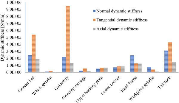
Using the dynamic stiffness data of each component calculated from Eq. (11), the overall machine dynamic stiffness was obtained as follows: 4.83 kN/mm in the X direction, 7.41 kN/mm in the Y direction, and 2.66 kN/mm in the Z direction.
3.2 The Elastic Deformation in High-Speed Camshaft Grinding
To accurately analyze the elastic deformation behavior during single-pass grinding process, the relationships between cam rotation angle, grinding wheel feed displacement, and time were calculated based on constant-linear-velocity grinding theory. By introducing time as an intermediate variable, a corresponding relationship between the feed displacement of the grinding wheel and the cam contour rotation angle was established. Table 3 presents the corresponding values of cam contour angle and time during high-speed grinding at a workpiece speed of vw = 100 1/min.
Table 3. Relationship between cam rotation angle and time
|
The contour angle [°] |
ω [rad/s] |
1/ ω |
Time of per 1° [ms] |
Total time [ms] |
|---|---|---|---|---|
|
0 |
6.8552 |
0.145875 |
0 |
0 |
|
1 |
7.1084 |
0.140679 |
2.17694 |
2.17694 |
|
2 |
7.3947 |
0.135232 |
2.26462 |
4.44157 |
|
3 |
7.9293 |
0.126115 |
2.42834 |
6.86992 |
|
··· |
··· |
··· |
··· |
··· |
|
357 |
10.472 |
0.095493 |
3.20705 |
1128.02 |
|
358 |
10.472 |
0.095493 |
3.20705 |
1131.23 |
|
359 |
10.472 |
0.095493 |
3.20705 |
1134.43 |
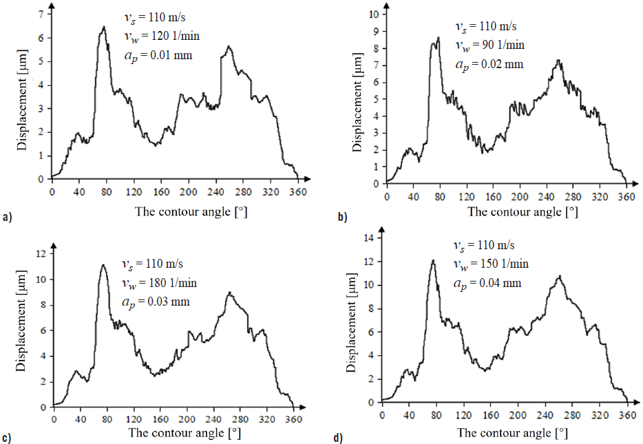
Figure 6 illustrates the relationship between the elastic deformation displacement of the camshaft and the cam profile rotation angle at a grinding wheel linear speed of vs = 110 m/s. The elastic deformation of the processing system increases initially and then decreases over both 0° to 180° and 180° to 360° rotation intervals.
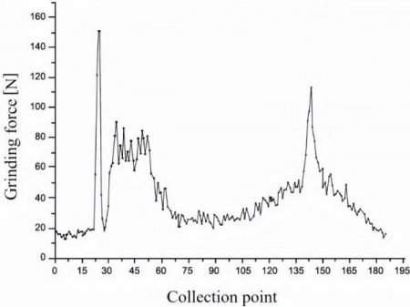
Compared with Fig. 7, it can be observed that the variation pattern of elastic deformation displacement across the full 0°–360° cam profile rotation during single-pass grinding closely aligns with the trend of the normal grinding force. For any given cam angle, the dynamic stiffness in high-speed grinding remains essentially constant. Therefore, according to Hooke’s law, an increase in grinding force at the same angle inevitably results in a greater elastic deformation displacement.
To further analyze the influence of grinding process parameters on the elastic deformation displacement of the camshaft during high-speed grinding, the experimental results were examined using both range analysis and variance analysis. The experimental data and the corresponding range analysis results are presented in Table 4.
According to Hooke’s law, the elastic deformation displacement during machining can be calculated by dividing the grinding force by the overall dynamic stiffness of the machine. These calculated values were compared with the experimental results, as shown in Table 4. The displacement error between the calculated and measured values was minimal, with a maximum deviation of only 5.56 %. It can be concluded that the experimental method is both accurate and reliable, and that both approaches yielding reasonably accurate elastic deformation displacements. Since elastic deformation is closely related to the dynamic stiffness of the machine, a higher stiffness results in smaller deformation under the same excitation force.
Table 4. The experimental data and extreme analysis of elastic deformation
|
No. |
Grinding speed [m/s] |
Workpiece speed [1/min] |
Grinding depth [μm] |
Normal grinding force [N] |
Displacement of test [μm] |
Displacement of calculation [μm] |
Error [%] |
|---|---|---|---|---|---|---|---|
|
1 |
90 |
90 |
10 |
31.88 |
6.888 |
6.595 |
4.26 |
|
2 |
90 |
120 |
20 |
41.04 |
8.856 |
8.489 |
4.14 |
|
3 |
90 |
150 |
30 |
49.92 |
10.76 |
10.326 |
4.03 |
|
4 |
90 |
180 |
40 |
58.79 |
12.591 |
12.161 |
3.42 |
|
5 |
110 |
90 |
20 |
40.08 |
8.637 |
8.291 |
4.01 |
|
6 |
110 |
120 |
10 |
29.95 |
6.475 |
6.195 |
4.32 |
|
7 |
110 |
150 |
40 |
55.28 |
12.108 |
11.435 |
5.56 |
|
8 |
110 |
180 |
30 |
50.93 |
11.080 |
10.535 |
4.92 |
|
9 |
130 |
90 |
30 |
48.37 |
10.332 |
10.006 |
3.16 |
|
10 |
130 |
120 |
40 |
54.32 |
11.642 |
11.236 |
3.48 |
|
11 |
130 |
150 |
10 |
28.77 |
6.199 |
5.951 |
4.00 |
|
12 |
130 |
180 |
20 |
37.48 |
8.095 |
7.753 |
4.23 |
|
13 |
150 |
90 |
40 |
40.53 |
8.746 |
8.384 |
4.14 |
|
14 |
150 |
120 |
30 |
35.91 |
7.769 |
7.428 |
4.39 |
|
15 |
150 |
150 |
20 |
32.65 |
7.058 |
6.754 |
4.31 |
|
16 |
150 |
180 |
10 |
26.7 |
5.762 |
5.523 |
4.15 |
As shown in Fig. 8, the grinding depth, grinding wheel speed, and workpiece speed are the primary process parameters affecting elastic deformation during high-speed camshaft grinding. Experimental results reveal that the variation pattern of the elastic deformation displacement throughout a single-pass grinding closely aligns with that of the normal grinding force. The maximum elastic deformation displacement increases with both grinding depth and workpiece rotational speed, but decreases with increasing grinding wheel’s linear speed. Therefore, to minimize elastic deformation in high-speed camshaft grinding, it is recommended to use a higher grinding wheel speed, a smaller grinding depth, and an appropriately selected workpiece speed.
3.3 The Relationship Between Grinding Feed Passes and Elastic Deformation
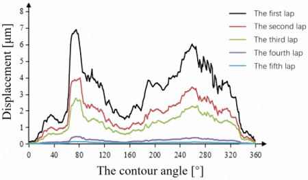
In the practical camshaft grinding, the total grinding allowance is typically removed through multi-pass grinding. To investigate the relationship between the number of grinding cycles and the elastic deformation during high-speed grinding, a multi-pass grinding deformation experiment was conducted. Under the process parameters of a grinding wheel speed of 90 m/s, a grinding depth of 0.01 mm, and a workpiece rotational speed of 90 1/min, the relationship between elastic deformation displacement and cam profile angle was analyzed, as illustrated in Fig. 6.
From Figure 9, the maximum elastic deformation displacement during the first grinding pass is 6.89 μm, accounting for 68.9 % of the preset grinding depth. In the second pass, the maximum elastic deformation decreases to 3.98 μm, or 39.8 % of the preset depth. During the third pass, the maximum elastic deformation further decreases to 2.66 μm, which is 26.6 % of the grinding depth. In the fourth pass, the maximum elastic deformation is reduced to 0.443 μm, corresponding to 4.43 % of the preset grinding depth, and by the fifth pass it drops to only 0.15 μm, just 1.48 % of the preset grinding depth. The results indicate that as the number of grinding cycles increases, the elastic deformation displacement gradually decreases. By the fifth pass, the elastic deformation displacement of the processing system is reduced to approximately 1 % of the preset grinding depth, making it almost negligible.
To further study the effect of multi-pass grinding on the elastic withdrawal of the processing system during the high-speed grinding, the actual grinding depth function is applied to the machine-tool stiffness based on Eq. (9).
As shown in Eq. (12) the expression is a monotonically increasing function. This indicates that, under a constant preset grinding depth, the actual material removal per pass increases proportionally with the number of grinding laps in each revolution. As the number of laps increases, the elastic rebound displacement of the system in each pass gradually decreases. Consequently, when the number of grinding cycles becomes sufficiently large, the elastic deformation in each lap approaches zero, and the actual grinding depth converges toward preset value. Therefore, increasing the number of grinding passes can effectively reduce the feed error caused by elastic deformation under a fixed grinding allowance.
4 CONCLUSION
Theoretical analysis and experimental modeling of depth-of-cut errors in the high-speed camshaft grinding were carried out, leading to the following conclusions:
1. The correlation between the feed displacement of the high-speed grinding wheel frame and the rotational angle of the camshaft contour was established. Experimental results reveal that the discrepancy between the theoretical and measured displacements is less than 5.56 %, thereby confirming the accuracy and reliability of the proposed model.
2. The dynamic stiffness characteristics of the critical components within the grinding process system were obtained through a combination of theoretical analysis and experimental validation. The findings reveal that the machine exhibits anisotropic stiffness, and that the grinding wheel spindle, workpiece spindle, and grinding carriage all possess insufficient dynamic rigidity.
3. The maximum elastic deformation displacement during high-speed camshaft grinding shows a positive correlation with both grinding depth and workpiece rotational speed, while exhibiting a negative correlation with the increase of linear speed of the grinding wheel.
4. As the number of grinding feed passes increases, the elastic deformation of the grinding wheel decreases significantly. When the number of passes reaches a certain threshold, the elastic deformation decreases to approximately 1 % of the preset grinding depth. In practical camshaft grinding processes, this approach effectively mitigates feed errors induced by elastic deformation.
References
[1] Wang, Y., Zhang, Y., Cui, X., Liang, X., Li, R., Wang, R., et al. High-speed grinding: from mechanism to machine tool. Adv Manuf 13 105-154 (2025) DOI:10.1007/s40436-024-00508-x.
[2] Wegener, K., Bleicher, F., Krajnik, P., Hoffmeister, H., Brecher, C. Recent developments in grinding machines. CIRP Annals 66 779-802 (2017) DOI:10.1016/j.cirp.2017.05.006.
[3] Liu, T., Deng, Z., Luo, C., Li, Z., Lv, L., Zhuo, R. Chatter detection in camshaft high-speed grinding process based on VMD parametric optimization. Measurement 187 110133 (2022) DOI:10.1016/j.measurement.2021.110133.
[4] Zhuo, R., Deng, Z., Li, Y., Liu, T., Ge, J., Lv, L., Liu, W. An online chatter detection and recognition method for camshaft non-circular contour high-speed grinding based on improved LMD and GAPSO-ABC-SVM. Mech Syst Signal Proceed 216 111487 (2024) DOI:10.1016/j.ymssp.2024.111487.
[5] Tang, H., Deng, Z.H., Guo, Y.S., Qian, J., Reynaerts, D. Depth-of-cut errors in ELID surface grinding of zirconia-based ceramics. Int J Mach Tools Manuf 88 34-41 (2015) DOI:10.1016/j.ijmachtools.2014.08.003.
[6] Meng, Q., Guo, B., Li, K., Wu, G., Zhao, H., Jia, J., et al. Stability prediction and optimization of multi-regenerative weak stiffness grinding system based on microstructured tool. Mech Syst Signal Proceed 208 111010 (2024) DOI:10.1016/j.ymssp.2023.111010.
[7] Wei, W., Xianying, F. Analysis of grinding force and elastic deformation in thread grinding process. Adv Mech Eng 5 187-188 (2013) DOI:10.1155/2013/827831.
[8] Badger, J., Murphy, S., O’Donnell, G. The effect of wheel eccentricity and run-out on grinding forces, waviness, wheel wear and chatter. Int J Mach Tools Manuf 51 766-774 (2011) DOI:10.1016/j.ijmachtools.2011.06.006.
[9] Yang, J., Zhu, R., Yue, Y., Dai, G., Yin, X. Nonlinear analysis of herringbone gear rotor system based on the surface waviness excitation of journal bearing. J Braz Soc Mech Sci 44 54 (2022) DOI:10.1007/s40430-021-03352-3.
[10] Payrebrune, K.M., Kröger, M. Effects of the Grinding Wheel Eccentricity and Waviness on the Dynamics of Tool Grinding. Appl Mech Mater 4537 128-138 (2017) DOI:10.4028/www.scientific.net/AMM.869.128.
[11] Pereverzev, P.P., Popova, A.V., Pimenov, D.Yu. Relation between the cutting force in internal grinding and the elastic deformation of the technological system. Russ Eng Res 35 215-217 (2015) DOI:10.3103/S1068798X15030156.
[12] Nosenko, V.A., Tyshkevich, V.N., Sarazov, A.V. Optimization of conditions for non-rigid workpieces flat grinding by elastic deformations controlling. Proc Eng 206 1173-1178 (2017) DOI:10.1016/j.proeng.2017.10.613.
[13] Yamada, T., Lee, H.S., Miura, K. Effect of contact stiffness of grinding wheel on ground surface roughness and residual stock removal of workpiece. Adv Mater Res 2631 797-797 (2013) DOI:10.4028/www.scientific.net/AMR.797.522.
[14] Mueller, S., Wirtz, C., Trauth, D., Klocke, F. Plastic deformability at micro-scale of fiber-reinforced ceramics with porous matrix during grinding. Proc Eng 207 119-124 (2017) DOI:10.1016/j.proeng.2017.10.748.
[15] Yin, T., Du, H., Zhang, G., Hang, W., To, S. Theoretical and experimental investigation into the formation mechanism of surface waviness in ultra-precision grinding. Tribol Int 180 108269 (2023) DOI:10.1016/j.triboint.2023.108269.
[16] Liu, T., Deng, Z., Lv, L., She, S., Liu, W., Luo, C. Experimental analysis of process parameter effects on vibrations in the high-speed grinding of a camshaft. Stroj Vestn-J Mech E 66 175-183 (2020) DOI:10.5545/sv-jme.2019.6294.
[17] Liu, T., Li, W., Deng, Z., Yao, Q., Tang, J., Yan, J., Kang, H. Chatter stability analysis for non-circular high-speed grinding process with dynamic force modelling. J Sound Vib 595 118782 (2025) DOI:10.1016/j.jsv.2024.118782.
[18] Oiwa, T., Kyusojin, A. Development of precise cylindrical grinding by ball centers: effect of dynamic stiffness on work profile. Precis Eng 14 237-242 (1992) DOI:10.1016/0141-6359(92)90021-N.
[19]Albertelli, P., Cau, N., Bianchi, G., Monno, M. The effects of dynamic interaction between machine tool subsystems on cutting process stability. Int J Adv Manuf Tech 58 923-932 (2012) DOI:10.1007/s00170-011-3465-5.
[20] Uriarte, L., Herrero, A., Zatarain, M., Santiso, G., Lacalle, L.N.L.D., Lamikiz, A., Albizuri, J. Error budget and stiffness chain assessment in a micromilling machine equipped with tools less than 0.3 mm in diameter. Precis Eng 31 (2007) 1-12. DOI:10.1016/j.precisioneng.2005.11.010.
[21] Shen, N., Li, J., Wang, X.D., Ye, J., Yu, Z.X. Analysis and detection of elastic deformations of the large-scale crankshaft in non-circular grinding. Appl Mech Mater 532 285-290 (2014) DOI:10.4028/www.scientific.net/AMM.532.285.
[22] Cha, K.C., Wang, N., Liao, J.Y. Stability analysis for the crankshaft grinding machine subjected to a variable-position worktable. Int J Adv Manuf Tech 67 501-516 (2013) DOI:10.1007/s00170-012-4501-9.
[23] Li, B., Cai, H., Mao, X., Huang, J., Luo, B. Estimation of CNC machine-tool dynamic parameters based on random cutting excitation through operational modal analysis. Int J Mach Tools Manuf 71 26-40 (2013) DOI:10.1016/j.ijmachtools.2013.04.001.
[24] Kareepadath Santhosh, D., Pušavec, F., Krajnik, P. Grinding of cemented carbide using a vitrified diamond pin and lubricated liquid carbon dioxide. Stroj Vestn-J Mech E 69 435-443 (2023) DOI:10.5545/sv-jme.2023.658.
[25] Robles-Ocampo, J., Jáuregui-Correa, J., Krajnik, P., Sevilla-Camacho, P., Herrera-Ruiz, G. Nonlinear Model for the Instability Detection in Centerless Grinding Process. Stroj vestn-J Mech E 58 693-700 (2012) DOI:10.5545/sv-jme.2012.649.
[26] Matsubara, A., Tsujimoto, S., Kono, D. Evaluation of dynamic stiffness of machine tool spindle by non-contact excitation tests. CIRP Annals 64 365-368 (2015) DOI:10.1016/j.cirp.2015.04.101.
[27] Xia, Y., Wan, Y., Luo, X., Wang, H., Gong, N., Cao, J., et al. Development of a toolholder with high dynamic stiffness for mitigating chatter and improving machining efficiency in face milling. Mech Syst Signal Pr 145 106928 (2020) DOI:10.1016/j.ymssp.2020.106928.
[28] Zhang, X.H., Deng, Z.H., Liu, W., Cao, H. Combining rough set and case based reasoning for process conditions selection in camshaft grinding. J Intell Manuf 24 211-224 (2013) DOI:10.1007/s10845-011-0557-x.
[29] Mi, L., Yin, G., Sun, M., Wang, X. Effects of preloads on joints on dynamic stiffness of a whole machine tool structure. J Mech Sci Technol 26 495-508 (2012) DOI:10.1007/s12206-011-1033-4.
[30] Ozlu, E., Budak, E., Molinari, A. Analytical and experimental investigation of rake contact and friction behavior in metal cutting. Int J Mach Tools Manuf 49 865-875 (2009) DOI:10.1016/j.ijmachtools.2009.05.005.
[31] Kopetskii, A.A., Nosenko, V.A., Tyshkevich, V.N. Influence of the shift of clamping forces on elastic deformations of the bearing ring in a jaw gripper. J Mach Manuf Reliab 43 55-59 (2014) DOI:10.3103/S1052618814010099.
[32] Deng, C., Liu, Y., Zhao, J., Wei, B., Yin, G. Analysis of the machine tool dynamic characteristics in manufacturing space based on the generalized dynamic response model. Int J Adv Manuf Technol 92 1411-1424 (2017) DOI:10.1007/s00170-017-0201-9.