

1 INTRODUCTION
With the expanding applications of robotics in industrial production, healthcare, and logistics, achieving high-precision force control remains challenging. Direct force measurement increases costs and suffers from environmental noise, while inherent nonlinear friction and inertial disturbances further degrade estimation accuracy—posing safety risks in robot-environment interactions that demand urgent resolution [1-3]. As external force estimation critically affects the safety of precision assembly, minimally invasive surgery, and collaborative robotics, sensorless force estimation methods that eliminate force sensors and compensate for disturbances algorithmically have become a key research direction with significant academic and practical value.
The ongoing advancement of artificial intelligence and robotics has driven remarkable progress in human-robot interaction, spurring continued deepening of related research. A systematic review of existing literature indicates that current methods for external force estimation can be broadly categorized into several main types:
In the field of physical sensor-based external force detection, researchers have developed various approaches. Phong et al. [4] estimated external forces using joint-mounted force sensors, enabling autonomous overload prevention. Phan et al. [5] employed distributed capacitive flexible sensor arrays to improve collision localization accuracy. Meng et al. [6] created a flexible 3D tactile sensing system for multi-dimensional force detection in bionic robotic hands. Zhu et al. [7] developed the vision-based DIGIT tactile sensor for contact force estimation. Huo et al. [8] combined ESO with ARFC using external force/torque sensors for precise manipulator control. Costanzo and Pirozzi [9] reviewed sensor-based techniques, noting that optical-tactile integration enhances accuracy. De Maria et al. [10] used tactile sensors with gravity compensation to extract interaction forces. While these methods achieve high accuracy and rapid response, their substantial manufacturing costs limit economic feasibility for large-scale industrial robot applications.
Several distinct approaches have emerged in hybrid detection methods that combine physical sensors with estimation algorithms: Guo et al. [11] developed a spiking neural network system using event-driven tactile sensors for efficient contact analysis. Dong et al. [12] employed extended state observers to estimate contact forces in industrial polishing by fusing robot body sensor data. Assa et al. [13] applied Kalman filtering to fuse multi-source force data, improving noise suppression and dynamic response. Birjandi et al. [14] combined inertial measurement unit (IMU) with state observers to enhance torque estimation, though requiring substantial computational resources. While these hybrid methods achieve higher accuracy, they remain limited by sensor costs and placement constraints – end-effector mounting simplifies modeling but cannot monitor forces along arm links [15]. These limitations have driven research toward more economical sensorless solutions.
Sensorless external force estimation methods have evolved through multiple approaches. De Luca and Mattone [16] established the theoretical foundation using generalized momentum theory for collision detection, subsequently refined by researchers [17-19] for human-robot collaboration. Alternative methods utilize internal sensor data like joint motor torque and angles [20], exemplified by Yuan et al. [21], who achieved accurate force estimation through motor torque analysis and pseudoinverse modeling. However, model-based methods face challenges in dynamic model accuracy. To address this, Li et al. [22] developed recursive parameter identification, while Kommuri et al. [23] employed high-order sliding mode observers for momentum dynamics compensation. Xiao et al. [24] proposed load identification to decouple interaction forces through static and dynamic load compensation. Recent innovations include: Ni et al. [25] designing compliance control with motor current feedback; Liu et al. [26] applying extended state observer (ESO) and nonlinear state error feedback control law (NLSEF) for disturbance compensation; Zhang et al. [27] combining momentum observers with admittance control; Zhu et al. [28] developing vision-based force estimation from compliant hand deformation; and Chua et al. [29] creating deep learning frameworks fusing vision and robot state data. These sensorless techniques reduce cost and complexity while promoting wider adoption of collaborative robots.
Building upon existing research in sensorless force estimation, this study specifically addresses two critical limitations of conventional generalized momentum observers: their dependence on linear friction models that cannot accurately describe nonlinear joint friction dynamics, and their fixed parameters that lack adaptability to changing operational conditions. To overcome these challenges while maintaining cost efficiency, we develop an enhanced friction compensation method based on an adaptive neuro-fuzzy inference system (ANFIS). Through comprehensive comparative evaluation against conventional fuzzy neural networks (FNN)—a hybrid model that integrates fuzzy logic’s reasoning capabilities with neural networks’ learning ability, particle swarm optimization, and least squares (LS) methods, our experimental results on a SCARA platform demonstrate that the proposed ANFIS-GM (Gaussian mixture) method achieves superior performance in friction modeling accuracy, external force estimation, and collision detection. This approach provides an effective solution for advancing high-precision robotic force control [30,31] in practical applications.
2 METHODS
This section presents the methodology for friction compensation and external force estimation in a SCARA robot. The robot dynamics were first modeled, incorporating the Stribeck friction model to capture nonlinear friction behavior. An adaptive neuro-fuzzy inference system (ANFIS) was then designed to identify friction parameters from velocity-torque data. The identified friction model was integrated into a generalized momentum observer for external torque estimation. To improve signal quality, a hybrid filtering strategy combining median and Butterworth filters with zero-phase correction was applied. This framework enables accurate friction compensation and robust force estimation for subsequent experimental validation.
2.1 Scara Robot Dynamics Modeling
For the purpose of force analysis, the SCARA robot (DELTA) is considered and idealized as a two-link structure, presented in Fig. 1.

Based on the two-link model in Fig. 1, the dynamics of the robot under no external load are formulated as:
In Equation (1), M(q) ∈ Rn×n denotes the inertia matrix, \(C\left( {q,\dot q} \right) \in {R^n}\) and Q(q) ∈ Rn represent the centrifugal/Coriolis force vector and gravitational torque vector, respectively; τm is the joint driving torque vector, and \(\ddot q\) denotes the joint acceleration vector.
Due to the horizontal configuration of the SCARA robot, the gravitational term G(q) is negligible. However, friction torques τf significantly affect motion accuracy and must be included in the model. Thus, the complete dynamic model becomes:
In Equation (2), τf denotes the vector of frictional torques.
2.2 Friction Modeling Based on the Stribeck Model
Robotic joint friction, particularly critical at low velocities, exhibits complex nonlinearities like static friction and the Stribeck effect, which are not captured by simple Coulomb-viscous models. To accurately characterize friction across all velocity regimes, the Stribeck model is adopted for its effectiveness in describing both the nonlinear low-speed behavior and the linear high-speed characteristics. Its mathematical representation is:
In Equation (3), fs denotes the static friction coefficient, Vs represents the Stribeck velocity, fc is the viscous damping coefficient, and ξi corresponds to the Stribeck curve decay coefficient, assigned a value of 2 in this study.
Figure 2 illustrates the characteristic Stribeck curve, showing the friction torque decreasing at low velocities, transitioning through the Stribeck effect, and increasing nearly linearly at high speeds.

2.3 Friction Parameter Identification Based on ANFIS
2.3.1 Takagi-Sugeno Model of Fuzzy Systems
The Takagi-Sugeno (T-S) fuzzy system [32] is a commonly used fuzzy inference model, where the consequent of its rules is a linear or nonlinear function of input variables. Let the input vector be x = [x1, x2, …, xn]T, and the jth fuzzy rule is: If x1 is X1i, … , xn is Xni, then yi = pj0 + pj1x1 + … + pjnxn, where j = 1, 2, …, m.
The firing strength αj for each rule is calculated as the product of the membership degrees. The final system output yj is the weighted average of all rule outputs:
In Equation (4), \({\bar \alpha _j} = {\alpha _j}/\sum\limits_{i = 1}^m {{\alpha _i}}\) represents the normalized firing strength of the jth rule, and yj denotes the weighted consequent output.
Let n denote the number of inputs, k = 1, 2, …, n denote the input index, and j = 1, 2, …, m, denote the rule index.
In Equation (5), \(\mu _k^j = {\mu _{X_k^j}}\left( {{x_k}} \right),{\mu _{X_k^j}}\left( {{x_k}} \right)\) denotes the membership function of the fuzzy set.
2.3.2 Construction of ANFIS
For friction identification of the SCARA robot, the ANFIS is trained using measured pairs of joint velocity and friction torque. The input vector is defined as x = [x1], where \({x_1} = \dot q\) denotes the joint angular velocity [rad/s]. The network output is y = [y1], where \({y_1} = {\widehat \tau _f}\) denotes the estimated friction torque [Nm]. Therefore, the input and output dimensions are n = 1 and r = 1, respectively.
In this study, “fuzzification” means converting each crisp input xk into a membership degree \({\mu _{X_n^j}}\left( {{x_n}} \right) \in \left[ {0,1} \right]\), which indicates how strongly xk belongs to the fuzzy set Xkj used in the jth rule. Gaussian membership functions are used:
where cij and σij are the center and width, respectively. The rule firing strength αj is then obtained by aggregating the membership degrees across all inputs, and the normalized firing strength \({\bar \alpha _j}\) is computed to weight the consequent outputs.
This paper adopts a fuzzy neural network structure combining a four-layer antecedent network and a consequent network, as shown in Figs. 3 and 4.
Antecedent network is responsible for fuzzifying the input and calculating rule applicability, including the input layer, membership function layer, rule layer, and normalization layer, whereas consequent network is composed of multiple parallel sub-networks, each sub-network outputs:
The system’s final output is:

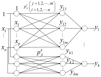
The ANFIS adopts the standard layered architecture: input layer → membership-function layer → rule layer → normalization layer → consequent/output layer (Fig. 3). Gaussian membership functions are used. Since there is one input (n = 1). In this study assign n = 1 Gaussian membership functions to x1, resulting in m = Mn = 5 fuzzy rules.
Accordingly, the membership-function layer contains 5 nodes, the rule layer contains 5 nodes, and the normalization layer contains 5 nodes. Connections between adjacent layers follow the standard ANFIS connectivity: the input is connected to all membership nodes, and each rule aggregates membership degrees from all inputs (fully connected between adjacent layers). The consequent part adopts first-order ANFIS consequents. For the jth rule, the consequent output is linear in the input, y1j = p1j0 +p1j1x1 and the overall output is obtained by the weighted sum of all rule consequents using normalized firing strengths.
As shown in Figs. 3 and 4, the proposed FNN follows a layered ANFIS structure. For clarity, Figs. 3 and 4 explicitly show the full connectivity between adjacent layers in the implemented model.
Learning Algorithm trains the network parameters (membership function centers cij and widths σij) using the gradient descent method, with the error function defined as:
In Equation (9), E denotes the error cost function, where ti and yi represent the desired and actual outputs, respectively.
The parameter update rule derived via first-order gradient optimization is given by:
{c_{ij}}\left( {k + 1} \right) = {c_{ij}}\left( k \right) – \beta \frac{{\partial E}}{{\partial {c_{ij}}}}, \hfill \\
{\sigma _{ij}}\left( {k + 1} \right) = {\sigma _{ij}}\left( k \right) – \beta \frac{{\partial E}}{{\sigma {w_{ij}}}}. \hfill \\
\end{gathered} \quad \quad (10)$$
In Equation (10), cij and σij denote the center and width of the membership function, respectively, while β > 0 is the learning rate, which can be adaptively adjusted during iterations.
The ANFIS does not output the Stribeck coefficients directly. Instead, it learns the nonlinear mapping \({\widehat \tau _f}\left( {\dot q} \right)\) from the measured torque–velocity data. After training, the learned torque–velocity relationship is sampled on a dense velocity grid (separately for forward and reverse motions if asymmetric friction is considered). The Stribeck friction model is then fitted to the sampled curve by nonlinear LS, yielding the Coulomb friction coefficients ( fc+, fc–), the Stribeck velocity coefficients ( Vs+, Vs–), the viscous coefficient fv, and the static friction coefficients ( fs+, fs–).
2.4 External Torque Observer Design
2.4.1 Generalized Momentum Observer
A generalized momentum-based torque observer is designed to estimate external joint torques using the robot’s state information and dynamic model. When external forces act on the robot, its dynamic behavior follows from Eq. (2) as:
In Equation (11), τext denotes the equivalent external torque acting on each joint. The robotic dynamic model possesses the following property:
The generalized momentum of the robotic system is defined as:
In Equation (13), P denotes the generalized momentum of the robot. Substituting Eqs. (11) and (12) into the time derivative of Eq. (16) yields:
Defining an observable for the momentum derivative leads to:
which
In Equation (16), r denotes the momentum residual, and K is the observer gain matrix. Under ideal conditions, the estimates \({\widehat C^T}\left( {q,\dot q} \right)\) and \({\widehat \tau _f}\) match their true values. Combining Eqs. (14) and (15) with the time derivative of Eq. (16) yields:
Applying the Laplace transform to this equation gives:
The equation reveals that in steady-state conditions, R(0) = r(0). Consequently, r can be interpreted as the observed external torque, expressed as:
2.4.2 External Torque Observer Based on Generalized Momentum and Friction Compensation
When a robotic arm interacts with external forces, additional torques are generated at its joints. Accurate analysis of these external torques therefore requires a precise dynamic model. The dynamics of the robot under external forces are described by the following equation:
The generalized momentum observer r, when integrated with the control scheme, is expressed as:
In Equation (21), \(\widehat r\left( t \right)\) denotes the estimate of τext, with initial momentum P(0) = 0. The observer gain matrix is defined as K = diag{K1, K2, …, Kn}. Differentiating both sides of Eq. (24) and applying the Laplace transform gives:
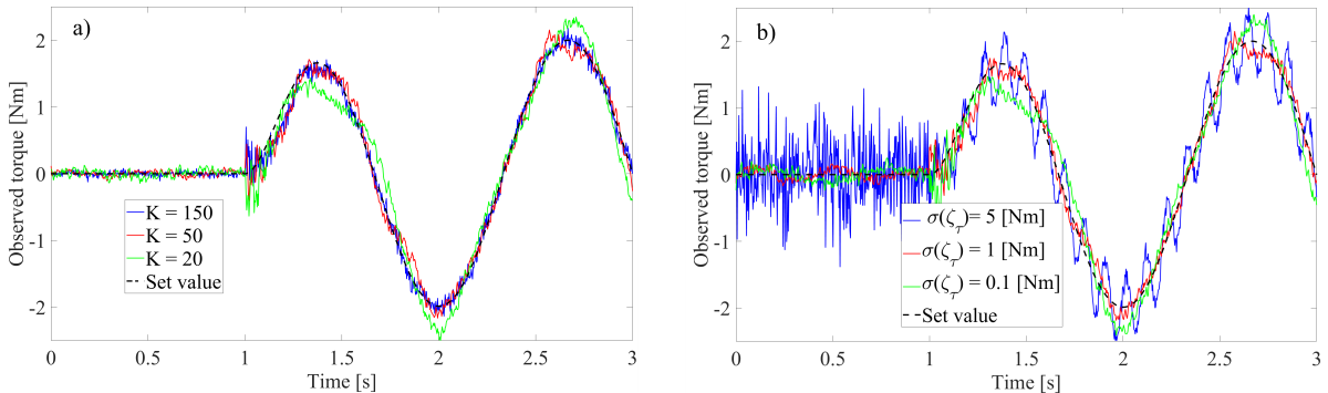
Based on Eq. (23), j = 1, 2, …, n, the observer gain K critically influences the dynamic performance: increasing K accelerates external torque tracking but amplifies measurement noise, while decreasing K smooths the signal but degrades tracking capability. For collision detection applications, a threshold is applied to the observed torque Rj to distinguish external forces from noise. To analyze the coupling effects of torque noise and observer gain, assuming negligible model error and Gaussian-distributed torque noise ζτ, the observed output for joint j under no external force can be expressed as:
Equation (24) allows for analyzing the impact of the noise ζτ on threshold determination. Applying the continuous-discrete transformation rule of s – (1 – z–1)Ts to Eq. (24) yields:
where Ts denotes the sampling period. Under this discretization, \({\widehat R_j}\left( k \right)\) follows a first-order autoregressive (AR1) process, whose variance is given by:
Here, αj = 1 / (KTs + 1) defines the autocorrelation coefficient. The estimation variance \(\operatorname{var} \left( {{{\widehat R}_j}} \right)\) decreases with lower observer gain K. Assuming Gaussian noise ζτj(k) with prob(| ζτj(k)| < 3σ(ζτj)) ≈ 0.997 and noise variance σ2(ζτj) = var(ζτj) for joint j, the detection threshold for Rj is determined by:
The detection threshold Θextj incorporates a safety margin Θτj to accommodate modeling inaccuracies and system uncertainties. This threshold increases proportionally with both torque measurement noise magnitude and observer gain K. To systematically analyze these coupled effects on dynamic performance and threshold selection, a simulation study was conducted using the SCARA robot platform.
Figure 5a shows torque estimation under different observer gains with fixed torque noise σ(ζτ) = 1 Nm. Higher gains amplify noise during unloaded operation (0 s to 1 s), causing estimation errors, and degrade tracking under external force (1 s to 2 s). Figure 5b displays results under varying noise with K = 50. Increased noise raises fluctuations during unloaded periods, necessitating higher detection thresholds. While tracking remains consistent for fixed gain, larger noise produces noisier interaction torque observations. Based on these analyses, observer gains are selected as K1 = 50 and K2 = 30 for Joints 1 and 2, respectively.
2.4.3 External Torque Observer Signal Filtering
High-frequency noise inherent in force measurements during human-robot interaction can significantly degrade the accuracy of observation. To enhance the robustness of the observer, this study proposes a hybrid filtering strategy that integrates a median filter with a Butterworth low-pass filter, an approach inspired by the ECG signal processing methodology of Menaceur et al. [34]. Moreover, to meet the stringent requirements of temporal alignment in both offline analysis and real-time control, a non-causal zero-phase filtering technique is implemented to eliminate phase distortion.
The raw joint torque signal r(t) is first processed by a median filter to eliminate transient impulse noise from data acquisition while preserving phase characteristics. This operation is mathematically defined as:
where \(\widehat r\left( {{t_i}} \right)\) denotes the filtered joint torque signal, r(tj) represents the original input signal, k defines the half-window length, and tj indicates the temporal index within the filtering window.
A median filter with a window size of 5(2k+1 structure) was implemented to optimally preserve signal edges and structural details.
Following median filtering for impulse noise removal, a Butterworth low-pass filter with 400 Hz sampling frequency is applied to suppress high-frequency noise. The filter design follows classical control theory [35], where sampling frequency should exceed the closed-loop bandwidth by 4 to 10 times to maintain discrete-time performance, satisfying:
To prevent excitation of robotic resonant modes and maintain control system stability, the closed-loop bandwidth must remain sufficiently below the dominant resonant frequency. This study adopts a reference bandwidth of fbw = 60 Hz . Based on these dynamic constraints and noise suppression requirements, the following filter specifications are defined: the passband cutoff frequency is set to fpass = 60 Hz with a maximum attenuation of Apass = −4 dB to ensure passband flatness, while the stopband cutoff is set to fstop = 150 Hz, with a minimum attenuation of Astop = −20 dB to effectively suppress high-frequency noise. The frequency response of the Butterworth filter is expressed as:
In Equation (30), n denotes the filter order and fc represents the cutoff frequency. The minimum filter order satisfying both passband and stopband specifications is determined by:
With the filter order determined as n = 4, the cutoff frequency is calculated to strictly satisfy the passband requirements, thus achieving optimal passband flatness:
Based on Eqs. (31) and (32), the Butterworth low-pass filter is designed with order n = 4v and cutoff frequency fc = 50 Hz.
The analog Butterworth filter prototype is discretized via the bilinear transform, resulting in the digital transfer function H(z). Its normalized form is expressed as:
Given the poles pk = exp( j(π/2)(2k + N – 1)/N), k = 1, 2, …, n, the denormalized transfer function is obtained from Eq. (35) as:
Using Eqs. (33) and (34), the bilinear transform converts the system from the analog to the digital domain as follows:
In Equation (35), Ts denotes the system sampling period, defined as Ts = 1/fs. The corresponding digital transfer function is:
In Equation (36), ai and bi represent the filter coefficients, with their specific values provided in Table 1.
Table 1. Filter coefficients
| Coefficient | Section 1 | Section 2 |
|---|---|---|
| b0 | 0.047 | 0.093 |
| b1 | 0.093 | 0.186 |
| b2 | 0.047 | 0.093 |
| a0 | 1 | 1 |
| a1 | -1.3 | -0.54 |
| a2 | 0.49 | 0.085 |
The digital transfer function H(z) is realized in the time domain as a linear constant-coefficient difference equation, which provides the programmable implementation of the filter:
However, the conventional causal Butterworth filter introduces nonlinear phase distortion. To overcome this limitation, forward-backward filtering is applied to the median-filtered signal \(\widehat r\left( {{t_i}} \right)\), thereby achieving zero-phase characteristics.
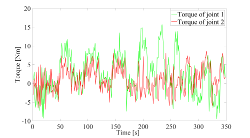
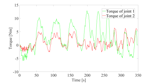
Figure 6 displays the original waveforms of the external torque signals acquired from Joints 1 and 2. The raw external torque signal was first processed with a median filter and subsequently smoothed using a Butterworth filter. The resulting waveform is presented in Fig. 7.
3 RESULTS AND DISCUSSION
3.1 Robot Experimental Platform Setup
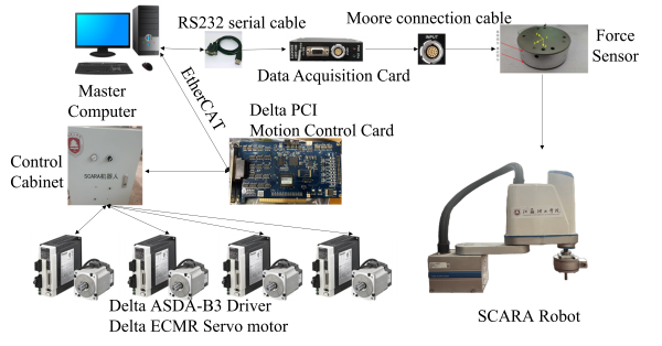
To validate the frictional compensation torque estimation method, a SCARA robot platform with EtherCAT communication was established for direct teaching experiments. The test setup (Fig. 8) integrates a control cabinet, an M4314A force sensor, an M8128 data acquisition card, and a PCI motion control card driven via EtherCAT bus.
3.2 Parameter Identification
Experimental data for parameter identification were collected using the setup in Fig. 9. Motor output torque was measured at harmonic drive output angular velocities spanning ±[0.01, 0.02, …, 1] rad/s. Data acquisition was performed at 400 Hz with 200 repeated trials per velocity point to ensure statistical reliability. All tests were conducted under controlled conditions: (25±2) °C ambient temperature, standard lubrication, and no external load.
The acquired dataset was randomly divided into training and testing subsets with a 70:30 ratio. The T-S model was trained using gradient descent with a maximum of 100 iterations and a batch size of 10. Specifically, 140 data points were used for training and 60 for testing. Through empirical tuning, the initial learning rate was set to 0.005. For friction parameter identification in the first two joints of the SCARA robot, a comparative evaluation was performed with a conventional FNN, along with the particle swarm optimization (PSO) [33] and LS methods, as summarized in Fig. 10.
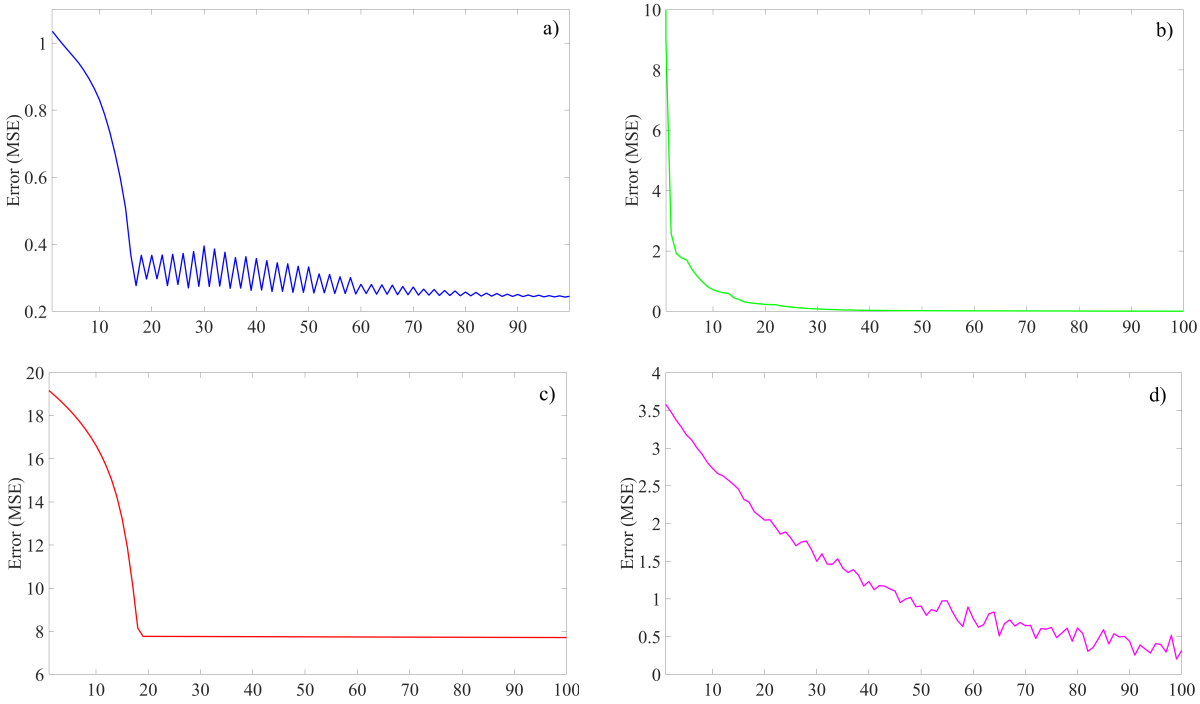
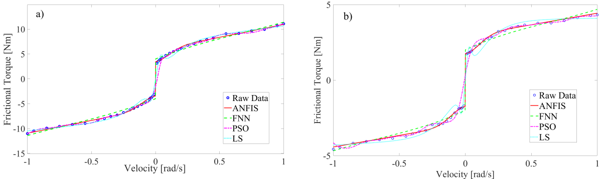
Friction parameters for the first two joints were identified from the acquired torque–velocity data using four methods: ANFIS, FNN, PSO, and LS method. The corresponding Stribeck curves are presented in Figs. 11a and b, respectively. In contrast, Fig. 10 compares the identification errors, highlighting the relative performance of each approach.
As shown in Fig. 10a, the ANFIS model shows lower training error than the other methods under the same training settings, indicating its suitability for friction torque modeling in this study.
Figure 11 presents the parameter identification results of the Stribeck friction model obtained using the four methods. The ANFIS-based approach achieves the minimal fitting error in characterizing the joint velocity-torque relationship, validating both the effectiveness of the Stribeck model for joint friction prediction and the superior accuracy of the proposed identification technique. The corresponding Stribeck parameters identified for the first two joints are summarized in Table 2.
Table 2. SCARA robot joint friction Stribeck friction coefficient
| Identification Method | ANFIS | FNN | PSO | LSM | ||||
|---|---|---|---|---|---|---|---|---|
| Joint | 1 | 2 | 1 | 2 | 1 | 2 | 1 | 2 |
| fc+ | 6.17 | 2.92 | 6.32 | 2.97 | 6.20 | 2.95 | 5.80 | 2.73 |
| fc– | -6.26 | -2.83 | -6.53 | -2.94 | -6.32 | -2.78 | -5.92 | -2.68 |
| Vs+ | 11.10 | 4.32 | 11.63 | 4.76 | 11.23 | 4.38 | 10.57 | 3.98 |
| Vs– | -11.01 | -4.57 | -10.79 | -4.86 | -10.98 | -4.60 | -10.37 | -4.28 |
| fv | 12.1787 | 5.0402 | 12.356 | 5.346 | 12.3325 | 5.052 | 11.56 | 4.68 |
| fs+ | 11.15 | 4.30 | 11.65 | 4.75 | 11.32 | 4.28 | 10.69 | 3.97 |
| fs– | -10.99 | -4.55 | -10.74 | -4.85 | -11.05 | -4.58 | -10.27 | -4.28 |
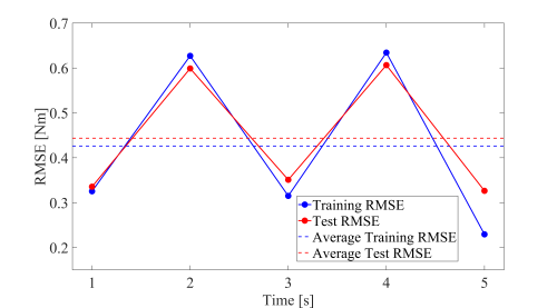
The five-fold cross-validation yielded a mean training of root mean square error (RMSE) of 0.43 Nm and a mean testing of RMSE of 0.44 Nm. The close agreement between these values, with a relative difference of only 4.1 %, along with a test error standard deviation of 0.15 Nm, indicates good generalization capability and robustness of the ANFIS-identified Stribeck model of the ANFIS-identified Stribeck model, confirming its reliability for friction modeling applications.
3.3 Friction Compensation for SCARA Robots
Based on the friction characteristics identified for the first two joints of the SCARA robot in the preceding section, the required compensation torque is formulated as:
In Equation (38), τcomp denotes the required compensation torque. Table 2 reveals significant asymmetry in the joint friction parameters between forward and reverse motion directions. The compensation strategy therefore dynamically selects parameters based on motion direction as follows:
{\left[ {f_c^ + + (f_s^ + – f_c^ + ){e^{ – {{(\dot q/V_s^ + )}^2}}}} \right] + {f_v}\dot q\quad \;\dot q > 0} \\
{ – \left[ {f_c^ – + (f_s^ – – \tau _c^ – ){e^{ – {{(|\dot q|/V_s^ – )}^2}}}} \right] + {f_v}\dot q\quad \dot q < 0} \\
{\min (|{\tau _{ext}}|,f_s^0) \cdot \operatorname{sgn} ({\tau _{ext}})\quad \quad \quad \quad \dot q = 0}
\end{array}} \right.. \quad \quad (39)$$
In Equation (39), τext denotes the external torque acting on the robot. The friction compensation is implemented as a feedforward component in the control system:
In Equation (40), τm denotes the total torque output from the robot motor, and τcontrol corresponds to the torque command from the controller.
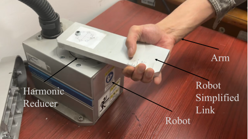
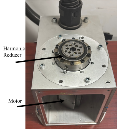
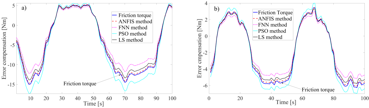
A velocity threshold of ±0.01 rad/s was applied near zero speed to smooth torque discontinuities from sign switching. The harmonic reducer was fixed horizontally with an attached link (Fig. 13) to serve as the robotic joint, eliminating gravity effects on friction identification.
The friction compensation curves presented in Fig. 14 were obtained by processing the acquired velocity and friction torque signals through a cascade of median and Butterworth filters. As shown in Fig. 14a and b, the ANFIS-based compensation achieves maximum friction torque errors of 0.263 Nm and 0.184 Nm for the two joints, lower than those obtained by FNN, LS, and PSO under the same dataset and settings. This indicates improved accuracy of ANFIS for friction modeling and compensation in this study.
3.4 Robot External Force Estimation Experiment Design
Direct teaching experiments were conducted to evaluate the proposed method’s effectiveness, comparing external torque estimation with and without friction compensation [36]. With joints in torque control mode and data sampled at 400 Hz, each configuration underwent 100 trials per condition under consistent experimental setup.
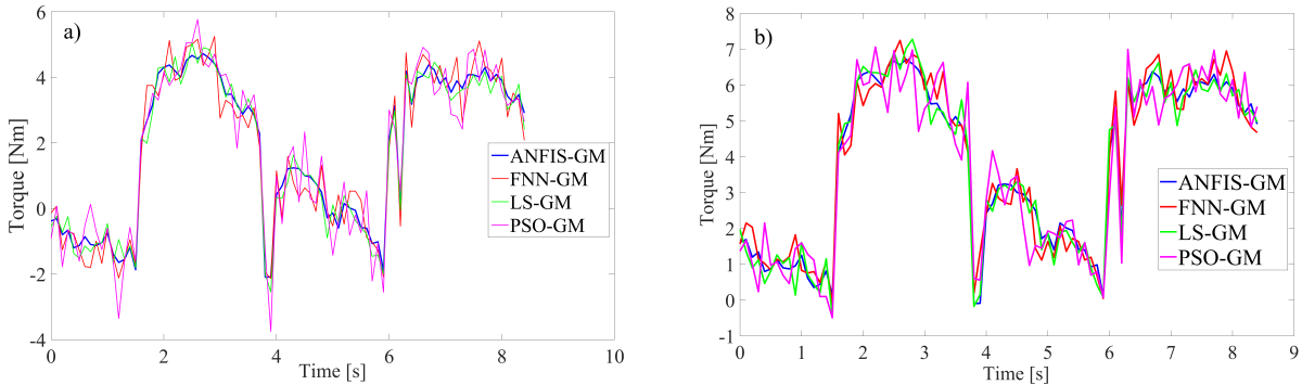
The robot was manually dragged from its zero position through specified angles while results were averaged for statistical reliability. Figure 15 presents a comparison of the compensated and uncompensated torque observations for the first joint obtained using different methods. Similarly, the torque measurement results for the corresponding second joint are shown in Fig. 16. All signals were processed with median and Butterworth filters.
Comparative analysis of external torque estimation with and without friction compensation indicates that:
- Incorporating the identified friction model reduces the bias and low-frequency drift caused by nonlinear friction, which improves the stability of the estimated external torque during free-motion (Figs. 15 and 16);
- Differences in waveform smoothness because the force-sensor reference may contain measurement noise and structural vibrations. Therefore, the effectiveness of the proposed observer is evaluated primarily by its agreement with the six-axis force sensor (ground truth) using quantitative metrics (RMSE, maximum absolute error (MAE), and R²) reported in Section 3.5 and Table 4. In these metrics, ANFIS-GM achieves the lowest RMSE/MAE and the highest R² across both joints, indicating closer agreement with the ground truth under the tested conditions.
3.5 Collision Detection Experiments
A dynamic trajectory tracking experiment was conducted on a SCARA robot to validate the method’s performance in simultaneous force estimation and collision detection during continuous motion with significant velocity/acceleration variations. The study systematically compares four observers (ANFIS-GM, PSO-GM, FNN-GM, conventional GM) using a six-axis force sensor as ground truth for comprehensive evaluation.
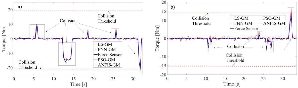
Figure 17 shows the torque variation curves during the experiment, where the robot encounters an obstacle while performing dynamic trajectory tracking. The six-axis force sensor mounted on the end effector provides real-time contact measurement data, establishing a ground truth benchmark for the quantitative evaluation of the observer.
To validate the superior performance of the ANFIS-GM method in collision detection, this study employs the following quantitative metrics for evaluation: detection delay (DD), peak error (PE), RMSE, and MAE, as shown in Table 3. The detailed formulas defining the RMSE and MAE metrics are provided in Section 3.5. Among them, the formula for detection delay is given by Δt = tdet – tstart , tdet is the moment when the estimated value first exceeds the threshold, tstart is the moment when the sensor signal first exceeds the threshold.
As shown in Fig. 17, collision intervals are determined based on the external torque reference derived from the force sensor, using the torque thresholds marked in Fig. 17. The boxed areas in the figures indicate collision moments, while the remaining parts correspond to collision-free motion moments. Collision detection performance is evaluated using the key metrics summarized in Table 3, including detection delay (DD), peak error (PE), and the RMSE/MAE with respect to the force-sensor reference during the collision interval. As shown in Table 3, ANFIS-GM achieves the smallest DD and PE and the lowest RMSE/MAE for both joints among the compared methods (PSO-GM, FNN-GM, and LS-GM), indicating faster detection and closer agreement with the ground truth.
Table 3. Performance evaluation of collision algorithms based on key metrics
| Index | ANFIS-GM | PSO-GM | FNN-GM | LS-GM | ||||
|---|---|---|---|---|---|---|---|---|
| Joint | 1 | 2 | 1 | 2 | 1 | 2 | 1 | 2 |
| DD [ms] | 0.2146 | 0.236 | 0.3786 | 0.3466 | 0.3209 | 0.2896 | 0.4673 | 0.4362 |
| PE [Nm] | 0.2353 | 0.0488 | 0.2862 | 0.1231 | 1.9034 | 0.5452 | 1.0384 | 0.8236 |
| RMSE [Nm] | 0.2556 | 0.2077 | 0.3431 | 0.2505 | 0.9824 | 0.5833 | 1.2463 | 0.7594 |
| MAE [Nm] | 0.8964 | 0.8909 | 2.3421 | 1.8791 | 2.9240 | 2.7101 | 4.3040 | 3.1971 |
3.6 Experimental Validation Based on Six-Dimensional Force Sensor
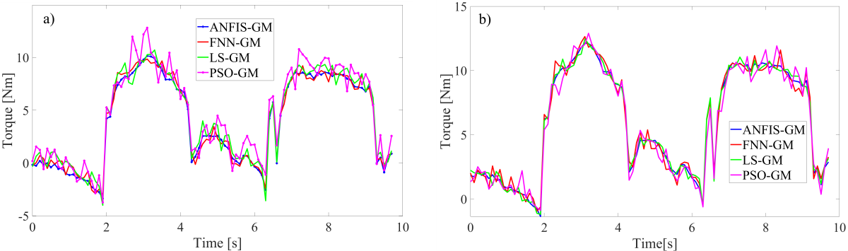
Based on the experimental data acquired from the force sensor, external torque estimation was conducted for Joints 1 and 2, with the results presented in Fig. 18.
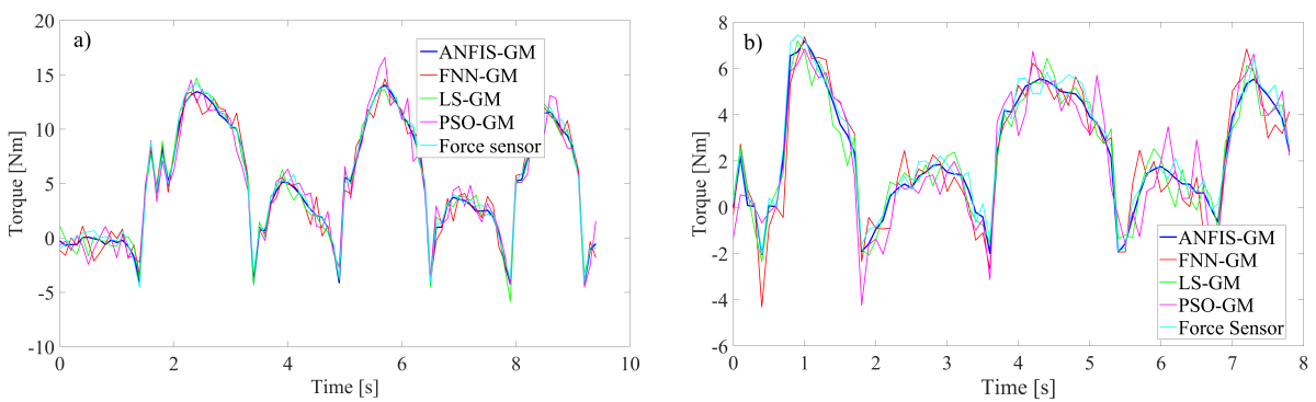
It should be noted that the six-axis force sensor signal may include high-frequency components caused by sensor noise, contact micro-vibrations, and structural dynamics. The objective of the observer is to estimate the underlying external torque rather than to reproduce the noise of the measurement device. For a fair comparison, the same median and Butterworth filtering procedure is applied to all compared torque signals (including the force-sensor-derived torque reference) before computing the quantitative metrics. Therefore, performance is assessed mainly through RMSE/MAE/R² with respect to the force-sensor reference, rather than by visual smoothness alone.
A comparative evaluation was conducted to assess the performance of the proposed fuzzy neural network-based friction-compensated torque observer against conventional methods, including the generalized momentum observer, particle swarm optimization (PSO)-based approach, and feedforward neural network-based technique. The quantitative assessment employs four performance metrics: RMSE, MAE, R2, and percentage improvement (PI).
RMSE quantifies the overall deviation between estimated and actual external forces, with particular sensitivity to larger errors:
In Eq. (41), N denotes the total number of samples, and τiext,sensor represents the external torque measured by the six-axis force sensor.MAE captures the worst-case estimation accuracy, particularly during abrupt force variations:
R2 metric quantifies the linear correlation between estimated and actual external forces, ranging from 0 to 1.
In Equation (43), \({\bar \tau _{ext,sensor}}\) denotes the mean value of the actual external force, while PI is denoted as:
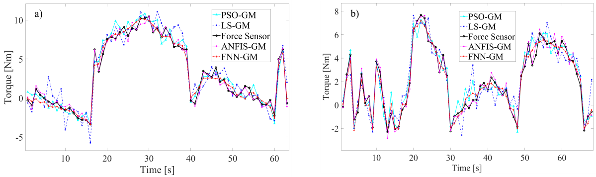
Table 4. The quantitative analysis and comparison of external force estimation methods
| Index | ANFIS-GM | PSO-GM | FNN-GM | LS-GM | ||||
|---|---|---|---|---|---|---|---|---|
| Joint | 1 | 2 | 1 | 2 | 1 | 2 | 1 | 2 |
| RMSE | 0.3089 | 0.2927 | 0.7932 | 0.6534 | 0.5786 | 0.5231 | 1.1845 | 1.0278 |
| MAE | 1.0496 | 1.2348 | 2.5495 | 2.4135 | 1.7548 | 1.9412 | 4.1450 | 4.4776 |
| R2 | 0.9863 | 0.9882 | 0.9093 | 0.9411 | 0.9517 | 0.9622 | 0.7978 | 0.8542 |
| Maximum error [N] | 1.0496 | 1.2348 | 2.5495 | 2.4135 | 1.7548 | 1.9412 | 4.1450 | 4.4776 |
| Minimum error [N] | 0.0062 | 0.0041 | 0.0482 | 0.0256 | 0.0023 | 0.0336 | 0.0370 | 0.0271 |
| Average Error [N] | 0.2436 | 0.2333 | 0.6398 | 0.5170 | 0.4582 | 0.4392 | 0.9122 | 0.8479 |
Table 5. Percentage improvement relative to the GM method
| Percentage improvement | ANFIS-GM [%] | PSO-GM [%] | FNN-GM [%] | |||
|---|---|---|---|---|---|---|
| Joint | 1 | 2 | 1 | 2 | 1 | 2 |
| RMSE | 73.9 | 71.5 | 33.0 | 36.4 | 51.2 | 49.1 |
| MAE | 74.7 | 82.4 | 38.5 | 46.1 | 57.7 | 56.6 |
| R2 | 23.6 | 15.7 | 14.0 | 10.2 | 19.3 | 12.6 |
| Maximum error [N] | 74.7 | 72.4 | 38.5 | 46.1 | 57.7 | 56.6 |
| Minimum error [N] | 43.6 | 84.9 | 30.3 | 5.5 | 79.1 | 24.0 |
| Average Error [N] | 73.3 | 72.5 | 29.9 | 39.0 | 49.8 | 48.2 |
As summarized in Tables 4 and 5, quantitative comparison with six-axis force sensor measurements confirms the superior performance of the ANFIS-GM method among the four evaluated approaches. The proposed method achieves the lowest RMSE (0.3089 Nm) and MAE (1.0496 Nm), representing Percentage Improvement of 73.9 % and 74.7 %, respectively, over the conventional GM observer. With a coefficient of determination (R²) of 0.9863 and the smallest maximum error (1.0496 Nm), ANFIS-GM demonstrates excellent correlation with ground truth measurements. The PSO-GM method ranks second in performance, substantially outperforming the conventional GM approach, while FNN-GM delivers moderate results. These findings validate that the ANFIS-Stribeck hybrid model integrated with the generalized momentum observer effectively compensates for nonlinear friction, providing an efficient solution for high-precision sensorless force control in applications such as direct teaching and human-robot interaction.
4 CONCLUSIONS
This study presents a novel approach for friction compensation and external force estimation in robotic systems by integrating an ANFIS with the Stribeck friction model. Unlike conventional generalized momentum observers that rely on linear friction models, the proposed ANFIS-Stribeck hybrid model effectively captures nonlinear friction dynamics and adapts to varying operational conditions. Experimental validation on a SCARA robot demonstrates that the proposed method significantly outperforms traditional techniques such as FNN, PSO, and LS in terms of identification accuracy and generalization capability. Specifically, the ANFIS-based method achieves a maximum torque error of 0.263 Nm for Joint 1 and 0.184 Nm for Joint 2, along with an 18.3 % reduction in RMSE and a 27.9 % reduction in MAE compared to conventional methods. The integration of median and Butterworth filters further enhances real-time noise suppression, leading to improved collision detection performance with reduced false alarm rates. These results validate the proposed approach as a robust and efficient solution for high-precision sensorless force control in applications such as direct teaching and human-robot interaction.
References
- Wang, J., Xu, B., Wang, X., Lai, J., Wei, X., Zhao, Z. et al. Control of SoftWearable robots for elbow assistance and rehabilitation: A simplified solution using disturbance observer and nonsmooth feedback. IEEE Trans Neural Syst Rehabil Eng 33 2988-2999 (2025) DOI:10.1109/TNSRE.2025.3594750.
- Feng, B., Wang, Z., Yuan, L., Zhou, Q., Chen, Y., Bi, Y. Towards safe motion planning for industrial human-robot interaction: A co-evolution approach based on human digital twin and mixed reality. Robot Comput-Integr Manuf 95 103012-103012 (2025) DOI:10.1016/j.rcim.2025.103012.
- Sato, F., Asano, Y., Higuchi, K.Y., Yamamoto, Y., Fujikawa, T., Sugiura, R. et al. Finite element method-based analysis of human arm bruise tolerance in blunt impact scenarios of human-robot interaction. Result Eng 27 106171 (2025) DOI:10.1016/j.rineng.2025.106171.
- Phong, L.D., Choi, J., Kang, S. External force estimation using joint torque sensors for a robot manipulator. IEEE Int Conf Robot Automat 4507-4512 (2012) DOI:10.1109/ICRA.2012.6224977.
- Phan, S., Quek, Z.F., Shah, P., Shin, D., Ahmed, Z., Khatib, O. Capacitive skin sensors for robot impact monitoring. IEEE/RSJ Int Conf Intel Robot Syst 2992-2997 (2011) DOI:10.1109/IROS.2011.6095083.
- Meng, X., Li, H., Sun, Y., Liu H., Wang F., Sun L. A Flexible Three-Axis Force Tactile Sensor for Human-Machine Interaction. Micronanoelectron Technol 58 1083-1087 (2021) DOI:10.13250/j.cnki.wndz.2021.12.006.
- Zhu, Y., Nazirjonov, S., Jiang, B., Colan, J., Aoyama, T., Hasegawa, Y. et al. Visual tactile sensor based force estimation for position-force teleoperation. IEEE Int Conf Cyborg Bionic Syst 49-52 (2023) DOI:10.1109/CBS55922.2023.10115342.
- Huo, Z., Yuan, M., Zhang, S., Zhang, X. Observer-based adaptive robust force control of a robotic manipulator integrated with external force/torque sensor. Actuators 14 116 (2025) DOI:10.3390/act14030116.
- Costanzo, M., Pirozzi, S. Optical force/tactile sensors for robotic applications. IEEE Instrum Meas Mag 24 28-35 (2021) DOI:10.1109/MIM.2021.9491003.
- De Maria, G., Natale, C., Pirozzi S. Force/tactile sensor for robotic applications. Sens Actuators A 175 60-72 (2012) DOI:10.1016/j.sna.2011.12.042.
- Guo, F., Yu, F., Li, M., Chen, C., Yan, Y., Li, Y. et al. Event-driven tactile sensing with dense spiking graph neural networks. IEEE Trans Instrum Meas 74 2508113 (2025) DOI:10.1109/TIM.2025.3541787.
- Dong, Y., Ren, T., Hu, K., Wu, D., Chen, K. Contact force detection and control for robotic polishing based on joint torque sensors. Int J Adv Manuf Technol 107 2745-2756 (2020) DOI:10.1007/s00170-020-05162-8.
- Assa, A., Janabi-Sharifi, F. A Kalman filter-based framework for enhanced sensor fusion. IEEE Sens J 15 3281-3292 (2015) DOI:10.1109/JSEN.2014.2388153.
- Birjandi, S.A.B., Kühn, J., Haddadin, S. Observer-extended direct method for collision monitoring in robot manipulators using proprioception and IMU sensing. IEEE Rob Autom Lett 5 954-961 (2020) DOI:10.1109/LRA.2020.2967287.
- Li, Q., Yuan, H., Ma, X., Song R. Collision position detection for robotic end-effector using force/torque sensor. Comput Integr Manuf Syst 27 109-117 (2021) DOI:10.13196/j.cims.2021.01.009.
- Luca, A.D., Mattone, R. Sensorless robot collision detection and hybrid force/motion control. Proc IEEE Int Conf Robot Automat 999-1004 (2005) DOI:10.1109/ROBOT.2005.1570247.
- Chien, S.H., Wang, J.H., Cheng, M.Y. Performance comparisons of different observer-based force-sensorless approaches for impedance control of collaborative robot manipulators. IEEE Conf Ind Cyberphysic Syst 326-331 (2020) DOI:10.1109/ICPS48405.2020.9274790.
- Fu, L., Zhao, J. Maxwell-model-based compliance control for human–robot friendly interaction. IEEE Trans Cognit Dev Syst 13 118-131 (2021) DOI:10.1109/TCDS.2020.2992538.
- Jia, Q., Xu, T., Chen, G., Sun, H., Wang, Y. Coordinated impedance control of robonaut based on disturbance observer. Robot 40 860-869 (2018) DOI:10.13973/j.cnki.robot.170464. (in Chinese)
- Zhang, Y., Jeong, C., Kim, M., Jin, S. Force-free control for direct teaching of a surgical assistant robot end effector with wire-driven bidirectional telescopic mechanism. Sensors 21 3498 (2021) DOI:10.3390/s21103498.
- Yuan, J., Qian, Y., Gao, L., Yuan, Z., Wan, W. Position-based impedance force controller with sensorless force estimation. Assem Autom 39 489-496 (2023) DOI:10.1108/AA-09-2018-0124.
- Li, Y., Zhu, L., Liu, J., Guo, S. Dynamic model identification for whole-arm compliance control. J Mech Eng 58 45-54 (2022) DOI:10.3901/JME.2022.03.045. (in Chinese)
- Kommuri, S.K., Han, S., Lee, S. External torque estimation using higher order sliding-mode observer for robot manipulators. IEEE/ASME Trans Mechatron 27 513-523 (2022) DOI:10.1109/TMECH.2021.3067443.
- Xiao, J., Dou, S., Zhao, W., Liu, H. Sensorless human-robot collaborative assembly considering load and friction compensation. IEEE Rob Autom Lett 6 5945-5952 (2021) DOI:10.1109/LRA.2021.3088789.
- Ni, T., Sun, X., Li, D., Zhao, Y., Zhang, P, Deng, Y. Compliance control strategy of parallel robot based on external force estimation. Trans Chinese Soc Agric Mach 53 443-451 (2022) DOI:710.6041/j.issn.1000-1298.2022.08.048. (in Chinese)
- Liu, X., Li, H., Fang, Y., Fan, D. Design and evaluation of a passive compliance control method of an offshore wind turbine blade grinding robot. Stroj Vestn-J Mech E 71 67-74 (2024) DOI:10.5545/sv-jme.2024.1121.
- Zhang, T., Hong, J., Liu, X. Dragging teaching method without torque sensor for robot based on elastic friction model. Trans Chinese Soc Agric Mach 50 412-420 (2019) DOI:10.6041/j.issn.1000-1298.2019.01.048.
- Zhu, Y., Hao, M., Zhu, X., Beteux, Q., Wong, A., Dollar, A.M. Forces for free: Vision-based contact force estimation with a compliant hand. Sci Robot 10 5046 (2025) DOI:10.1126/scirobotics.adq5046.
- Chua, Z., Jarc, A.M., Okamura, A.M. Toward force estimation in robot-assisted surgery using deep learning with vision and robot state. IEEE Int Conf Robot Automat 12335-12341 (2021) DOI:10.1109/ICRA48506.2021.9560945.
- Durairaj, S.P. Quantitative sequential modelling approach to estimate the reliability of computer controlled pneumatically operated pick-and-place robot. Stroj Vestn-J Mech E 71 28-35 (2024) DOI:10.5545/sv-jme.2024.999.
- Zhou, L., Liu, Y. Kinematics-based tracking control method for operational robotic arm under multi-environmental constraints. Stroj Vestn-J Mech E 71 389-401 (2025) DOI:10.5545/sv-jme.2025.1301.
- Al-Darraji, I., Kakei, A.A., Ismaeel, A.G., Tsaramirsis, G., Khan, F.Q., Randhawa, P., et al. Takagi–Sugeno fuzzy modeling and control for effective robotic manipulator motion. Comput Mater Continua 71 1011-1024 (2021) DOI:10.32604/cmc.2022.022451.
- Zhao, Y., Luo, J., Li, Y., Zhang, T., Ma, H. An optimal design method of hydrostatic turntable based on FPSO algorithm. Stroj Vestn-J Mech E 71 402-409 (2025) DOI:10.5545/sv-jme.2025.1366.
- Menaceur, N.E., Kouah, S., Derdour, M. Adaptive filtering strategies for ECG signal enhancement: A comparative study. Int Conf Pattern Anal Intell Syst Algeria 1-6 (2024) DOI:10.1109/PAIS62114.2024.10541144.
- Astrom, K.J., Wittenmark, B. Computer-Controlled Systems: Theory and Design (1996) Dover Publications, New York.
- Wang, Z., Li, X., Wu, J. A Direct Teaching Method of Robot by Estimating External Torque. Mach Des Manuf 4 268-272 (2024) DOI:10.19356/j.cnki.1001-3997.20231017.013.