


1 INTRODUCTION
The growing demand for renewable energy has positioned wind power as one of the most promising sources of sustainable electricity generation. Wind turbines, as the central components of wind energy systems, have undergone significant advancements in design and performance. The inherently unstable nature of wind flow and the operational variability of turbines create additional challenges that must be addressed to fully understand and optimize their aerodynamic performance. The aerodynamic performance of horizontal-axis wind turbines has been widely investigated using analytical, experimental, and computational approaches, with computational fluid dynamics (CFD) simulations becoming one of the most widely used tools for performance prediction and blade design optimization [1].
Numerical modeling and simulation of unsteady and/or nonuniform flows around wind turbines have thus emerged as indispensable tools for researchers and engineers aiming to enhance turbine efficiency and reliability with fewer resources [2-5].
Incorporating the atmospheric boundary layer (ABL) into the context of wind turbine dynamics is important for understanding how larger turbines behave in real-world conditions [3-4]. The ABL refers to the layer of air that is influenced by the presence of the Earth’s surface, and its wind speed profile can vary significantly with height. The changing wind profile has a significant impact on the aerodynamic performance of wind turbines, especially when rotor diameter increases. For large turbines, the incoming wind speed at the rotor top can differ significantly from that at the rotor hub or bottom, causing variations in aerodynamic forces and contributing to overall turbine efficiency. Variable speed operation plays a key role in optimizing energy capture under fluctuating wind conditions. The unsteady flow around the turbine, including wake turbulence, blade-vortex interactions, and the changing wind profile due to the ABL, makes it challenging to accurately predict its performance through experimental means alone. Computational approaches, such as CFD, including increasingly popular large-eddy simulations (LES), allow for a more detailed investigation of flow around the turbine. These high-fidelity simulations account for interactions between wind speed variations, rotor dynamics, and wake characteristics, enhancing turbine design and operational strategies [6-8]. Accurate prediction of the wake flow behind wind turbines is essential for evaluating aerodynamic performance and turbine interactions within wind farms [9].
Wang et al. [10] offer valuable insights into how nacelle-induced variations in wind speed can influence turbine performance, emphasizing the role of both atmospheric conditions and the turbine’s geometry. Understanding how the ABL modifies the incoming wind profile is crucial for optimizing rotor design and control strategies, particularly as turbines grow in size. The interplay of blade geometry, rotational speed, wind turbulence, nacelle interaction, and ABL require careful design and operation of wind turbines. This approach maximizes energy capture while reducing fatigue and wear on components. The continuing increase in turbine dimensions also introduces additional challenges related to blade manufacturing, inspection, and maintenance. Recent studies have investigated advanced robotic technologies for wind turbine blade servicing in demanding offshore environments, further emphasizing the need for reliable aerodynamic and structural analyses throughout the turbine life cycle [11]. The aerodynamic performance of wind turbines is governed by complex interactions between the rotor blades and the surrounding unsteady flow, influenced by variable wind profiles with height, wind turbulence, wake dynamics, and operational conditions. Early research efforts primarily relied on experimental techniques to study these phenomena. Pioneering wind tunnel studies established essential knowledge on blade aerodynamics and wake formation; however, limitations in spatial and temporal resolution constrained a thorough understanding of unsteady effects [12]. Guo et al. [13] contribute to the field by providing detailed experimental data on wake characteristics, which can help with the design and development of adequate operational strategies for wind turbines, leading to enhanced efficiency and reduced wake-related issues (losses and noise). Experimental investigations, such as wind tunnel measurements and particle image velocimetry (PIV) studies, provide valuable datasets for validating numerical models of wind turbine aerodynamics [14]. Recent work by Zhang et al. [15] has enhanced the understanding of wake behavior at various scales, highlighting discrepancies between scaled models and full-scale turbines, and accentuating the need to investigate wind turbines at their full size and in real operating conditions.
The advent of CFD revolutionized wind turbine research by enabling detailed simulations of flow behavior. Reynolds-averaged Navier-Stokes (RANS)-based models have been widely adopted for their computational efficiency in steady-state analyses. Several studies have applied RANS turbulence models to predict aerodynamic loads and flow structures around rotating wind turbine blades [16]. Studies, such as those by Sørensen and Hansen [17], have demonstrated the capability of RANS models to predict blade loading and overall power output under steady and uniform inflow conditions. Despite their utility, RANS models often fail to capture critical unsteady features such as wake turbulence and dynamic stall, particularly in scenarios involving transient wind or variable rotational speeds.
LES and detached eddy simulation (DES) have emerged as more robust alternatives, offering improved accuracy in resolving transient flow features and turbulent structures in wind turbine wakes. Martínez-Tossas et al. [18] employed LES to explore the impact of atmospheric turbulence on wind turbine wakes, highlighting the intricate interplay between inflow turbulence and wake recovery. Similarly, Kang et al. [19] demonstrated the effectiveness of LES in capturing dynamic stall phenomena and vortex shedding in rotating blades, providing deeper insights into the transient forces acting on wind turbines. The LES results reveal a significant impact of forest density on the normalized mean wind shear just above the canopy and within the rotor-swept area. Higher forest densities lead to increased wind shear above the canopy, affecting wind turbine performance. Additionally, the study notes that forest density affects the development and recovery of wind turbine wakes, with denser forests potentially mitigating the added turbulence from turbines [20]. However, these turbulence models are still very demanding in terms of computational resources and are used less frequently than RANS-based models.
In addition to turbulence modeling, the role of operational strategies, such as variable speed control, has gained increasing attention in recent years. Modern wind turbines often operate at variable rotational speeds to optimize energy capture across various wind conditions. While studies, such as those by Schulz et al. [21], have investigated the effects of yaw misalignment and operational strategies on wake dynamics, the impact of variable speed operation on unsteady flow behavior remains underexplored. Existing CFD studies assume constant rotational speeds, thereby neglecting the dynamic interaction between the turbine and the variable wind. Graham et al. [22] provided a detailed analysis of the unsteady aerodynamic forces on horizontal axis wind turbines under turbulent conditions, vital for enhancing turbine design and performance. A study by Zhao et al. [23] offers important insights into aerodynamic optimization methods applicable to wind turbine design, enhancing efficiency and minimizing noise.
Moreover, recent research has emphasized the significance of multi-physics simulations that integrate structural dynamics and aerodynamics. Blade element momentum theory coupled with finite elements has been utilized to capture the aeroelastic behavior of wind turbines under unsteady conditions [24]. These hybrid approaches offer valuable insights into load variations; however, their applicability to transient variable-speed scenarios is limited. There is a pressing need for comprehensive CFD frameworks that accurately model the effects of variable operational speeds on both near-field and far-field flow phenomena.
This study addresses the recognized research gap by conducting a comprehensive numerical analysis of nonuniform flow (varying with height) around a large wind turbine that operates at variable rotational speeds, employing CFD simulations. It is a continuation and advancement of the previous study focusing on uniform inflow [25]. The main goals here are to explore the resulting flow characteristics, including the actual aerodynamic performance of wind turbines in real operating environments, wake dynamics, and interactions between blades and vortices, particularly under variable rotational speed. We analyze how speed fluctuations influence aerodynamic performance through quantitative and qualitative measures such as power output and flow development and stability.
2 METHODS
2.1 Computational Domain and Geometry
The wind turbine blade is divided into 47 distinct airfoil sections, categorized into three main groups based on their function and location along the span (Fig. 1). These sections ensure smooth transitions between the hub and the aerodynamic blade, optimizing the balance between structural integrity and aerodynamic performance. The first six airfoils, starting from the center of rotation, are circular in shape. These sections form the foundation of the blade’s root and are designed for a smooth transition from the cylindrical hub to the aerodynamic airfoil shapes. This configuration reduces structural stress at the root and enables better load distribution from the blade to the turbine shaft. While these sections do not contribute significantly to lift generation, they play a vital role in maintaining the structural strength of the blade. The middle portion of the blade, spanning 35 airfoil sections, constitutes about 80 % of the blade length. These sections consist of the Delft University, The Netherlands, airfoil profiles, which are specifically designed and widely used in wind energy applications. The gradual non-linear twist and taper change/variability of these sections along the blade span is introduced since the sections operate in quite different operating conditions (relative velocity, angle-of-attack, etc.). The final six airfoil sections comprise the C-96 blade tip, a specialized design that mitigates tip losses and enhances aerodynamic efficiency. This part of the blade is meant to reduce tip vortices, which are a major source of energy loss, turbulence, and noise. This design should also ensure better performance in yawed flow conditions, which are commonly encountered in real-world wind turbine operations.
The blade is subjected to three primary aerodynamic forces (Fig. 1): lift (L), drag (D), and thrust (T). Each force plays a distinct role in determining the energy extraction and structural loads experienced by the turbine.
The simulation layout was designed to model an isolated rotor with a diameter of DB = 96 m in actual operating conditions (subject to wind speed that varies with height). The complete blades, including streamlined regions, cylindrical root sections and intermediate blending sections are modeled, while the tower is not included in the current study in order not to interfere with the rotating part of the domain. The stationary, outer part of the computational domain (stator) is shaped like a cuboid, starting 100 m fore and extending 300 m aft of the wind turbine rotor, with a rectangular cross-section of 240 m height and 320 m width (Fig. 1b). This shape is chosen to ensure a satisfactory blockage ratio and to adequately represent the vertical (height-dependent) velocity profile. Additionally, these dimensions ensure that the rotor is positioned sufficiently far from the boundaries to minimize numerical artifacts and boundary effects, while allowing the development of the variable-height inflow and capturing all relevant flow dynamics. The rotating, inner part of the computational domain is shaped like a cylinder with a diameter of 120 m and a total length of 70 m (20 m upstream and 50 m downstream of the wind turbine, respectively). The wind turbine rotor is placed symmetrically in the spanwise direction, ensuring the turbine is centrally located within the domain. This configuration allows for height-dependent flow conditions on both sides of the rotor and simplifies the analysis of flow patterns, including wake effects and the interaction of the turbine with the surrounding wind field. The layout mirrors the operational environment of a real wind turbine, considering the variation of wind speed with height.
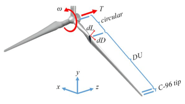
Fig. 1. Wind turbine: geometry schematic with forces
The turbine analyzed in this study corresponds to a large horizontal-axis wind turbine with a rotor diameter of 96 m and a rated power of approximately 2.5 MW, achieved at a rated wind speed of 15 m/s.
2.2 Computational Meshes
For accurate numerical simulations, three different unstructured computational meshes (coarse, medium, and fine) were generated to discretize the entire computational domain, differing in the level of resolution of the aerodynamic interactions near the rotor blades and the far-field flow. The medium grid, consisting of approximately 4.69 million control volumes (MCV), is illustrated in Fig. 2.
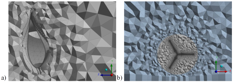
Fig. 2. Computational mesh: a) inflation layer around the blade, and b) mesh around the turbine, covering the rotor and stator
The mesh refinement strategy was primarily focused on achieving high resolution in the vicinity of the rotor blades in order to accurately capture complex flow features. A locally refined mesh region was therefore applied around the rotor to ensure detailed representation of the blade aerodynamics while maintaining a manageable overall number of computational volumes. To reduce mesh complexity and computational cost, a small portion of the extreme blade tip geometry was truncated (approximately the final 3 % of the blade span). In this region the chord length is also considerably smaller, and consequently the contribution of the truncated section to the overall rotor swept area is nearly negligible. However, the outer aerodynamic blade region responsible for the main aerodynamic loading remains fully represented in the computational model. Although this simplification does not fully capture the flow features near the very tip of the blades, it still provides valuable insight into the overall rotor performance and wake dynamics.
The fine unstructured grid used in the simulations contains approximately 7.26 MCV, representing a compromise between adequate spatial resolution in critical regions and acceptable computational cost. Near the blade surfaces, inflation layers were applied to accurately resolve the boundary layer and improve grid quality. The first layer height was set to 0.1 mm, enabling fine near-wall resolution and reliable turbulence modeling.
To evaluate grid independence, simulations were performed using three meshes with increasing resolution (1.97 MCV, 4.69 MCV, and 7.26 MCV). The comparison of global aerodynamic parameters, such as the power coefficient Cp, showed only minor differences between the medium and fine meshes, confirming that the numerical results are effectively mesh-independent. Consequently, the fine grid with approximately 7.26 MCV was adopted for the final simulations to ensure adequate resolution of the blade boundary layers and wake structures.
The boundary layer mesh consists of multiple inflation layers with a gradual expansion ratio, providing accurate resolution of the near-wall flow. The near-wall resolution corresponds to y+ values in the range of approximately 1–5 over most blade surfaces, ensuring proper boundary layer resolution when using the SST turbulence model.
2.3 Governing Equations
The foundation of the CFD simulations for the unsteady flow around the wind turbine rotor is based on the Navier-Stokes equations. These fundamental equations governing fluid motion describe how the velocity, pressure, and other fluid properties evolve over time. The Navier-Stokes equations are derived from the principles of mass conservation, momentum conservation, and energy conservation. In real-world fluid flows, turbulence is a common phenomenon that significantly affects the performance and efficiency of wind turbines. A turbulence model is necessary to accurately simulate turbulent flows around the rotor. For this study, the Reynolds-averaged Navier-Stokes (RANS) equations are used to model turbulence, with the k-ω shear stress transport (SST) turbulence model.
The k-ω SST model is a hybrid turbulence model that combines the advantages of two different turbulence models: the k-ε model (used in the free-stream) and the k-ω model (used near solid boundaries). This model is particularly suitable for simulating the flow around wind turbines, as it accurately predicts boundary layer separation and vortex shedding phenomena crucial for capturing the aerodynamics of the blades. The chosen models are characterized by the following equations:
+
\frac{\partial}{\partial x_j}(\rho k v_j)
=
\frac{\partial}{\partial x_j}
\left[
\left(
\mu+\frac{\mu_t}{\sigma_k}
\right)
\frac{\partial k}{\partial x_j}
\right]
+\mu_t S^2
-\rho\beta^{*}k\omega.
\tag{1}$$
+
\frac{\partial}{\partial x_j}(\rho\omega v_j)
=
\frac{\partial}{\partial x_j}
\left[
\left(
\mu+\frac{\mu_t}{\sigma_\omega}
\right)
\frac{\partial\omega}{\partial x_j}
\right]
+
\frac{\alpha}{\nu_t}\mu_t S^2
–
\rho\beta\omega^2
+
D_\omega
\left(
\frac{\partial k}{\partial x_j},
\frac{\partial\omega}{\partial x_j}
\right).
\tag{2}$$
where k is the turbulent kinetic energy, ω the rate of energy dissipation, xj the spatial coordinate, vj the component of the velocity vector, μ the dynamic viscosity, μt is the turbulent viscosity, α, β and β* are the model constants, σk is the turbulent Prandtl number for k, σω a turbulent Prandtl number for ω, Dω a cross-diffusion term, νt kinematic turbulent viscosity, and ρ the air density.
2.4 Simulation Setup
The simulations were conducted using ANSYS Fluent with a quasi-steady setup to analyze the nonuniform, turbulent flow around a rotating wind turbine rotor. Height-variable wind speeds were applied at the inlet, while multiple angular velocities Ω of the rotor, varying roughly between 0.4 rad/s and 1.8 rad/s, were considered to assess the turbine’s performance under different operational conditions. The moving reference frame (MRF) model was employed to simulate the rotational motion of the blades, with the computational domain split into rotating and stationary sub-regions. Boundary conditions were established to simulate the flow around the wind turbine rotor accurately and ensure stable convergence of the results.
The inlet was defined as a velocity inlet with a specified height-variable wind speed profile corresponding to the operational conditions obtained in field measurements by employing user-defined functions. Figure 3 shows the distribution of wind speed at various heights across different months of the year.
The vertical wind speed profile used as the inlet boundary condition was approximated using a power-law formulation commonly applied for atmospheric boundary layer flows:
where v(y) represents the wind velocity at height y, vref is the reference wind speed measured at the hub height yref , and α is the Hellmann shear exponent describing the vertical wind shear. For the present study, the reference velocity was vref = 6.7 m/s at the hub height vref = 80 m, corresponding to the atmospheric conditions recorded during the November measurement campaign. The Hellmann exponent used in the present analysis was α = 0.28, obtained by fitting the experimental wind speed measurements.
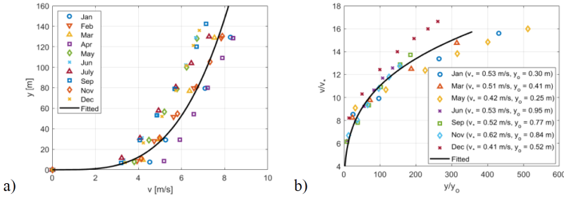
Fig. 3. The distribution of wind speed over vertical distance; a) vertical distance from the ground, and b) explanation
Figure 3 illustrates the distribution of wind speed over vertical distance, where v represents the wind speed, v* indicates the shear stress velocity, y is the vertical distance from the ground, and yo denotes the roughness height. The experimental data used for validation originate from the EOLOS wind energy research facility at the University of Minnesota, USA. The measurements were conducted during a field campaign in 2014 and include vertical wind speed profiles as well as operational turbine data [21]. These measurements were used both to construct the inflow boundary condition and to validate the numerical results presented in this study. The lower panel illustrates the velocity scaling within the atmospheric boundary layer, where the shear stress velocity v* is estimated from the logarithmic velocity profile. The measured data indicate that the average wind speed varies approximately 3.5 times between a height of 10 m and the highest elevation of the turbine blade at 129 m. The velocity distribution from November was selected as the representative inlet boundary condition for the simulations.
The atmospheric boundary layer inflow was therefore represented by prescribing a height-dependent velocity profile derived from the EOLOS field measurements. Although detailed turbulence spectra were not imposed at the inlet, the turbulence structure of the flow was modeled using the SST turbulence model. Terrain roughness effects were implicitly represented through the measured velocity distribution, while the ground boundary was treated as a stationary no-slip wall.
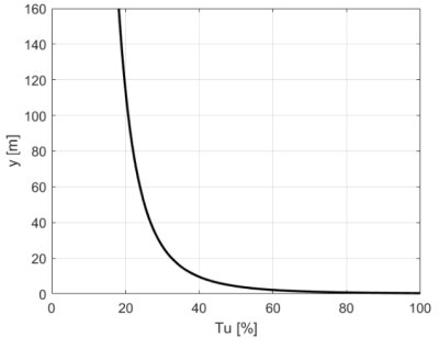
Fig. 4. Turbulence intensity over vertical distance from the ground
At the inlet, constant values of turbulence intensity (Tu = 5 %) and turbulent viscosity ratio (μt/μ = 10) were prescribed. In addition, the height-dependent velocity profile implicitly represents the atmospheric turbulence structure. A semi-empirical relationship, Tu ≈ 2.4/(v/v*), was used to characterize the decrease of turbulence intensity with height [26-28]. The turbulence intensity decreases from approximately 0.35 at 10 m above the ground to 0.19 at 140 m, which is consistent with the measured EOLOS atmospheric boundary layer data (Fig. 4).
At the outlet, a pressure outlet condition with zero-gauge pressure was applied, allowing the flow to exit the domain naturally without adverse pressure gradients. The rotor blades were treated as rotating wall boundaries with a no-slip condition, ensuring that the fluid velocity at the blade surface matched the blade’s rotational velocity and accurately capturing the interaction between the fluid and the blade surfaces. The lower side of the outer cuboid, representing the ground, was modeled as a stationary no-slip wall boundary. These boundary conditions were chosen to balance computational efficiency with the physical accuracy required to capture the complex flow dynamics around the turbine.
Preliminary tests using a sliding mesh approach and unsteady simulations were also performed under selected operating conditions. To quantitatively assess the applicability of the quasi-steady approach, additional comparisons between steady RANS (MRF) and unsteady URANS (sliding mesh) simulations were carried out for three representative tip speed ratios. The unsteady simulations were performed over seven complete rotor revolutions using a time step of dt = T/180. Table 1 presents the comparison of global aerodynamic coefficients, where Cm denotes the nondimensional torque coefficient, and Ct represents the thrust coefficient. Only minor differences were observed between the time-averaged aerodynamic coefficients obtained using both approaches. Therefore, the quasi-steady MRF approach was adopted for the present parametric study.
Table 1. Comparison of global aerodynamic coefficients for steady RANS (MRF approach) and unsteady URANS (sliding mesh approach) at the medium grid
| λ | 7 | 9 | 11 |
|---|---|---|---|
| Cm-RANS | 0.0590 | 0.0520 | 0.0400 |
| Cm-URANS | 0.0597 | 0.0516 | 0.0391 |
| ΔCm-URANS | 0.0002 | 0.0002 | 0.0002 |
| Ct-RANS | 0.6639 | 0.8755 | 1.0573 |
| Ct-URANS | 0.6764 | 0.8810 | 1.0472 |
| ΔCt-URANS | 0.0019 | 0.0016 | 0.0023 |
3 RESULTS AND DISCUSSION
This chapter first elucidates the results of the performed simulations of the flow around a wind turbine, considering height-variable wind speeds at the inlet and different angular velocities of the rotor. The reference wind speed at hub height (80 m) for the selected inflow case is approximately 6.7 m/s. This value corresponds to the measured atmospheric boundary layer conditions during the November measurement campaign. Consequently, the obtained turbine power values remain significantly below the rated power of the turbine.
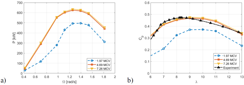
Fig. 5. Computational results: a) turbine power P versus angular velocity Ω, and b) power coefficient Cp versus tip speed ratio λ
The power output of the turbine generally increases steadily with the rotor’s angular velocity, reaching its peak at the optimal angular velocity of approximately 1.25 rad/s (Fig. 5a).
At the optimal angular velocity, the turbine also operates at maximum aerodynamic efficiency, extracting the highest energy from the wind. Beyond this optimal speed, however, the power begins to decline. The reduction in power results from flow separation, increased drag, and turbulence, all of which decrease the overall energy conversion efficiency. These results confirm the complex nature of turbine performance, where power generation does not directly correspond to the rotor’s angular velocity. Instead, efficiency is influenced by geometric and aerodynamic factors as well as wake dynamics at both lower and higher rotational speeds. This analysis emphasizes the necessity of operating the turbine within its optimal speed range to maximize energy output and prevent excessive mechanical loads or aerodynamic inefficiencies resulting in performance losses at suboptimal speeds. Figure 5a also illustrates how numerical results become independent of the mesh with its appropriate refinement, particularly in the boundary layer and near the leading edge of the blade’s airfoils.
The turbine power coefficient Cp indicates the proportion of power harnessed from the wind compared to the total wind power available. This is often analyzed alongside the tip speed ratio λ, which represents the relationship between the speed of the blade tips and the wind speed, as depicted in Fig. 5b. The curves plotted on the graph represent the following conditions:
(i) Computation (blue, red and yellow curves with markers):
- Results of numerical simulations of quasi-steady, turbulent nonuniform flow.
- By increasing the size and quality of computational grids (from 1.97 MCV to 7.26 MCV), the numerical results approach the measured values.
- For finer meshes, the optimal tip speed ratio is approximately λ ≈ 9, but satisfactory wind turbine operation can be expected in a wider range, 7 < λ < 12.
(ii) Measurement (black curve with triangular symbols):
- Results of experimental data [24].
- It shows a peak around λ = 8.5 and then slightly declines.
- It closely matches the numerical values obtained at the finest grid. Small discrepancies can be explained by the small differences in modeled and actual geometry, smoothing of the inflow profile by the power function, and some unresolved flow phenomena (flow transition and separation, dynamic stall, small-scale turbulence structures, etc.).
Overall, it can be stated that very satisfactory correspondence between numerical and experimental values is achieved. The maximal power coefficient is correctly calculated (and the critical importance of operating the turbine at or near its optimal tip speed ratio to maximize efficiency and power output is highlighted), while the value of optimal tip speed ratio can be estimated with a relative error of 5 %. It should be noted that experimental results are obtained in real operating conditions (that are stochastic) and on actual geometry (that is more complex than the modeled one, which omits the blade tips, tower, and aft part of the wind turbine nacelle). Also, a relatively standard computational model is employed, but special care is taken while modeling and meshing (it appears that root sections of the blades and the central region of the rotor are important when simulating, as is accurate representation and refined cell size in the streamlined portion of the blades). Finally, the correct inflow conditions significantly increase the accuracy of numerical results (as can be confirmed by comparing the current results with the ones provided in [25]). The close agreement between the measured and computed results validates the employed and represented simulation methodology, including the choices and definition of the turbulence model, boundary conditions, and computational mesh. It also demonstrates that the numerical model is reliable for studying wind turbine performance under different operating conditions. All results presented here were obtained for a single selected measured input velocity profile in November. For other velocity profiles (illustrated in Fig. 3), slightly different absolute values would likely be observed (due to the unavoidable influence of the Reynolds number, etc.). Still, they would probably remain within the variation range of the presented aerodynamic coefficients.
To quantify the agreement between numerical and experimental results, the RMSE between the computed and measured Cp values over the range of tip speed ratio 6 < λ < 13 was evaluated, showing a small deviation of approximately 0.020. Mean absolute error was also checked over the same range of operating conditions, and an even smaller value of 0.017 was obtained.
Figure 6 depicts the variation of the thrust coefficient Ct as a function of the tip speed ratio λ. At lower values, around λ ≈ 7, the thrust coefficient is approximately 0.67. As λ increases, Ct rises steadily, reflecting the increasing axial force exerted on the rotor at higher rotational speeds relative to the wind speed. While the thrust force does not directly contribute to torque generation since torque is produced by tangential forces, it plays a critical role in the structural design and stability of the wind turbine. Higher thrust forces translate to greater loads on the turbine’s tower and foundation, especially under high wind speed conditions. Understanding this variation is essential for ensuring the safe withstanding of these forces by the turbine structure while maintaining operational efficiency.
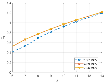
Fig. 6. Thrust coefficient Ct versus tip speed ratio λ
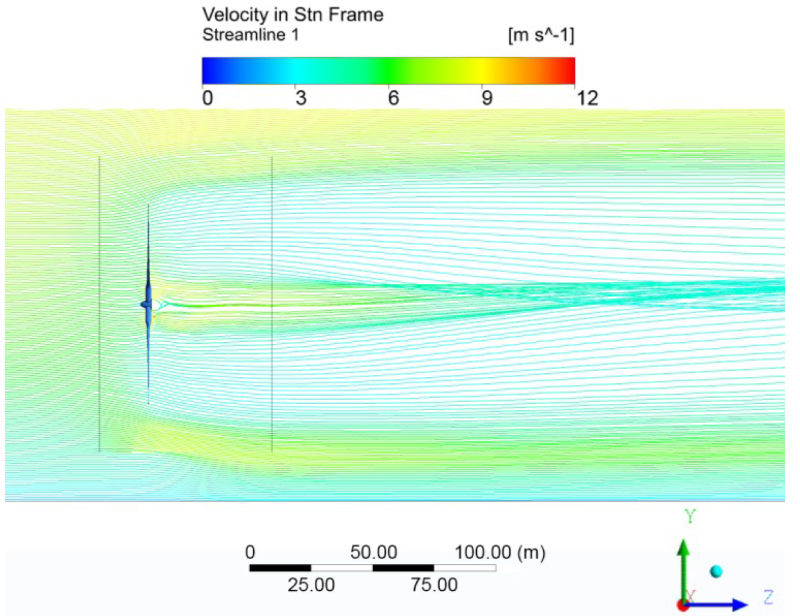
Fig. 7. Velocity streamlines in the stationary frame around the wind turbine rotor and through the computational domain at λ = 9
Figure 7 represents qualitative flow visualization by showing streamlines colored by velocity magnitude in the stationary frame.
The color scale on the left indicates velocity magnitudes ranging from 0 m/s (blue) to 12 m/s (red). Higher velocities (yellow/red regions) are concentrated in the central and top parts of the domain (influenced by both the rotor geometry change from the streamlined to the circular region as well as the height-dependent inflow). We can also observe the effect of the ground surface that slightly accelerates the adjacent flow. Lower velocities (blue/green areas) are apparent downstream of the wind turbine rotor, which extracts the power from the wind. Since the wind turbine operates near its optimal tip speed ratio, the resulting flow appears smooth and organized. Slight asymmetry (bending upwards) is a consequence of the asymmetric inflow and the existence of the ground. Some minor localized flow separation or recirculation regions are visible only near the blade roots and tips. This type of visualization is particularly useful in wind turbine aerodynamics, as it helps to understand wake formation, turbulence intensity, and velocity gradients.
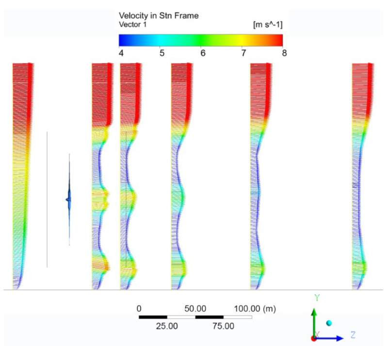
Fig. 8. Velocity vectors at several streamwise locations through the computational domain at λ = 9
Figure 8 qualitatively illustrates how the axial inflow (following the power law with height) changes by interacting with the wind turbine rotor. To better illustrate the development of the velocity profile in the symmetry plane, the velocity range has been reduced to 0 m/s to 8 m/s. Again, red areas indicate zones of higher velocity magnitudes, while blue areas depict regions of decelerated flow, primarily downstream of the streamlined, operational portions of the blades. The resulting velocity profiles are notably nonlinear right aft of the rotor, and they slowly stabilize further downstream. Nonetheless, the significant effect and large spatial scales of wind turbine wakes are adequately represented. This kind of analysis is quite useful and important when arranging the wind turbines within a wind farm.
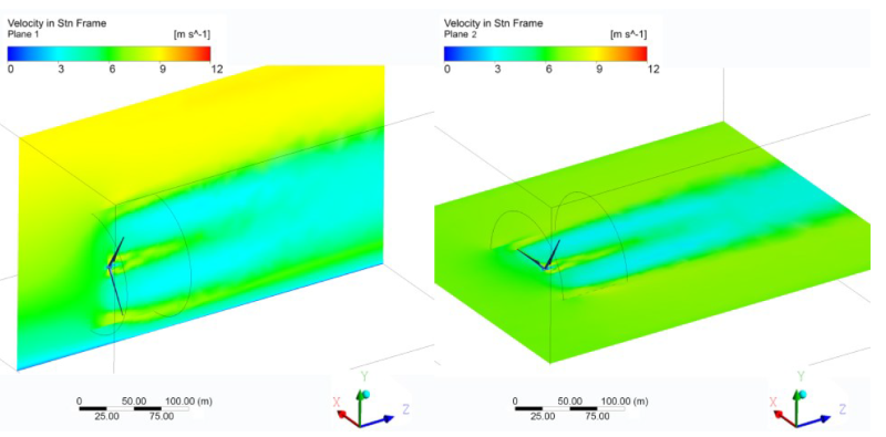
Fig. 9. Velocity contour distribution throughout the computational domain at λ = 9
Figure 9 illustrates the overall velocity distribution throughout the entire computational domain, offering an overview of the flow behavior from the inlet to the outlet in two perpendicular planes.
At the entrance to the domain, the velocity changes with height according to the power law. At the rotor hub height of 80 m, the inflow speed is approximately 6.7 m/s, which was also used as the reference velocity. The nonuniform but smooth inflow begins to interact with the domain’s internal components, i.e., the wind turbine rotor. The highest resulting velocities are observed in the central part and near the blade tips. The increased velocity is due to the accelerated flow as it interacts with the blade surfaces, which can create localized high-shear regions. These areas are critical for understanding where the flow energy is utilized or dissipated. As the flow moves downstream, its velocity gradually decreases. Far behind the rotor, the turbulence begins to dissipate, and the flow starts to stabilize. Eventually, a more uniform velocity field is observed farther downstream, signifying that the flow has returned to a quasi steady-state condition with minimal disturbances.
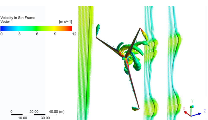
Fig. 10. Velocity vectors at several locations in the computational domain at λ = 9, together with vortical structures shed from the blades
Figure 10 shows velocity vectors at three streamwise locations (fore and aft of the wind turbine rotor) together with the iso-surfaces of constant vorticity (colored by velocity magnitude) that illustrate coherent wake structures shedding from the blades (dominantly from the tip and root sections).
These vortices are created by the interaction between the high-speed flow over the blade surfaces and the slower-moving fluid around them. The turbulent areas indicate where flow separation occurs and highlight the energy losses resulting from the rotor’s operation. Since the wind turbine rotor operates near its optimal conditions, vortex structures originate mainly from the outer blade region and root sections. Because the exact blade tip geometry was simplified in the present numerical model, the detailed structure of the tip vortex cannot be fully resolved; therefore, the presented results should be interpreted qualitatively. These insights are crucial for optimizing the blade design to minimize turbulence and reduce noise levels.
Due to the simplified blade geometry used in the present numerical model, detailed tip vortex structures are not fully resolved. Nevertheless, the obtained flow field still provides useful insight into the overall aerodynamic behavior of the rotor and wake development.
The primary sources of noise in this flow system arise from turbulence, vortex shedding, and flow separation. Turbulent structures and high-shear areas in the wake of the blades contribute to generating pressure fluctuations, which result in acoustic noise. Furthermore, the interaction between the high-speed flow over the rotor blades and the surrounding slower fluid creates vortex trails, which also produce noise due to the fluctuating forces present in the wake.
4 CONCLUSIONS
This study demonstrates the application of advanced CFD simulations to analyze the aerodynamic performance of a large wind turbine operating under height-variable, nonuniform wind speed conditions (in ABL). By employing a quasi-steady simulation approach with the k-ω SST turbulence model, the research has provided critical insights into the flow dynamics around wind turbine blades, including wake behavior, blade-vortex interactions, and their impact on aerodynamic efficiency.
The results highlight the nonlinear relationship between power output and angular velocity, with the turbine achieving peak performance at an optimal rotational speed (Ω = 1.25 rad/s). Beyond this point, power output diminishes due to flow separation, turbulence, and increased drag forces, emphasizing the need for precise control strategies to maintain operation within the optimal range. Similarly, the power coefficient Cp analysis validates the simulation’s accuracy and wide applicability by closely matching experimental results, with RMSE of 0.02 over the range 6 < λ < 13, peaking at a tip speed ratio λ of approximately 9, which marks the turbine’s maximum efficiency regime. These findings underscore the critical importance of operating turbines at their optimal tip speed ratio to maximize energy capture and minimize aerodynamic losses.
The thrust coefficient increases with tip speed ratio, highlighting the need to balance aerodynamic performance with structural loading. The predicted flow field successfully captures the main wake structures and aerodynamic features, providing useful insight into rotor performance under realistic inflow conditions.
This study proposes a methodology for analyzing nonuniform flow around a wind turbine rotor in variable speed operations. Despite the quasi-steady approach and the simplified blade tip representation, the close agreement with available experimental data confirms the accuracy of the computational setup and the adopted turbulence model. The findings highlight the importance of accurately prescribing atmospheric inflow conditions for turbine performance prediction and can support the design and control strategies for large-scale horizontal-axis wind turbines under realistic operating conditions.
A particular contribution of this study is the CFD analysis of the actual full-scale turbine geometry, which shows good agreement with experimental measurements and confirms the reliability of the adopted numerical methodology.
Future research could further enhance these findings by integrating more realistic environmental scenarios, utilizing advanced simulation methods such as LES, and adopting multi-physics approaches that combine structural dynamics and aerodynamics to provide a more comprehensive understanding of turbine behavior.
References
- Zha, R., Wu, S., Cai, C., Liu, X., Wang, D., Peng, C., et al. A review on performance calculation and design methodologies for horizontal-axis wind turbine blades. Energies 18 435 (2025) DOI:10.3390/en18020435.
- Sun, Z., Zhu, W., Jané, E., Wang, X., Shen, W.Z., Ferrer E. Sound propagation analysis of a 10 MW wind turbine: Influence of the tower, operational states, and atmospheric conditions. Renew Energy 255 123842 (2025) DOI:10.1016/j.renene.2025.123842.
- Khezri, M., Maghrebi, M.J., Mahmoodi, E., Ritschel, U. Reconstructing the upwind field of wind turbines using LiDAR data. Sustain Energy Technol Assess 80 104382 (2025) DOI:10.1016/j.seta.2025.104382.
- Wen, J., Liu, C., Zhang, S., Zhou, L., Tang, H., Xia, Y., et al. Wake dynamics and coherence modes of vertical-axis wind turbines: The role of atmospheric boundary layer. Phys Fluids 37 067123 (2025) DOI:10.1063/5.0271326.
- Wang, Y., Lu, P., Zhou, Y., Ge, M., Li, R. Impact of atmospheric stability on wind farm performance: Insights from internal boundary layer dynamics. Energy 321 135157 (2025) DOI:10.1016/j.energy.2025.135157.
- Svorcan, J., Wang, J. M., Griffin, K.P. Current state and future trends in boundary layer control on lifting surfaces. Adv Mech Eng 14 (2022) DOI:10.1177/16878132221112161.
- Nielsen, J., Bhaganagar, K. Using field data-based large eddy simulation to understand role of atmospheric stability on energy production of wind turbines. Wind Eng 43 625-638 (2019) DOI:10.1177/0309524X18824540.
- Li, Z., Han, R., Gao, P., Wang, C. Analysis and implementation of a drag-type vertical-axis wind turbine for small distributed wind energy systems. Adv Mech Eng 11 (2019) DOI:10.1177/1687814019825709.
- Amiri, M.M., Shadman, M., Estefen, S.F. A review of physical and numerical modeling techniques for horizontal-axis wind turbine wakes. Renew Sustain Energy Rev 193 114279 (2024) DOI:10.1016/j.rser.2024.114279.
- Wang, X., Liu, Y., Wang, L., Ding, L., Hu, H. Numerical study of nacelle wind speed characteristics of a horizontal axis wind turbine under time-varying flow. Energies 12 3993 (2019) DOI:10.3390/en12203993.
- Li, Y., Li, L., Ni, G., Li, X., Tan, J., He, K. Comprehensive performance evaluation of sliding-bearing wind turbine gearboxes. Stroj Vest- J Mech E 71 231-241 (2025) DOI:10.5545/sv-jme.2024.1239.
- Hansen, M.O.L., Sørensen, J.N., Voutsinas, S., Sørensen, N., Madsen, H.A. State of the art in wind turbine aerodynamics and aeroelasticity. Prog Aerosp Sci 42 285-330 (2006) DOI:10.1016/j.paerosci.2006.10.002.
- Guo, X., Li, Y., Li, R., Ma, Y., Wei, K. A wind tunnel experimental study on the wake characteristics of a horizontal axis wind turbine. J Therm Sci 34 145-158, (2024) DOI:10.1007/s11630-024-2074-1.
- Fritz, E., Boorsma, K., Ferreira, C. Experimental analysis of a horizontal-axis wind turbine with swept blades using PIV data. Wind Energy Sci 9 1617-1629 (2024) DOI:10.5194/wes-9-1617-2024.
- Zhang, X., Tao, M., Zhang, M., Zhu, R., Wang, S., Li, B., et al. Aerodynamic and wake characteristics for full-scale and model-scale 5 MW wind turbines using data-driven modal decomposition. Ocean Eng 318 120131 (2025) DOI:10.1016/j.oceaneng.2024.120131.
- Wang, W.-Y., Ferng, Y.-M. Numerical prediction of the aerodynamics and aeroacoustics of a 25 kW horizontal axis wind turbine. J Mech 40 299-312 (2024) DOI:10.1093/jom/ufae024.
- Sørensen J.N., Hansen, M.O.L. Rotor performance predictions using a Navier-Stokes method. Proc ASME Wind Energy Symp AIAA-98-0025 52-59 DOI:10.2514/6.1998-25.
- Martínez-Tossas, L.A., Churchfield, M.J., Meneveau, C. Optimal smoothing length scale for actuator line models of wind turbine blades based on Gaussian body force distribution. Wind Energy 20 1083-1096 (2017) DOI:10.1002/we.2081.
- Kang, S., Yang, X., Sotiropoulos, F. On the onset of wake meandering for an axial flow turbine in a turbulent open channel flow. J Fluid Mech 744 376-403 (2014) DOI:10.1017/jfm.2014.82.
- Vita, G., Adedipe, T., Hellsten, A. Impact of forest density on atmospheric boundary layer flow and turbulence for wind energy applications. Research Square (2024) DOI:10.21203/rs.3.rs-4631421/v1.
- Schulz, C., Letzgus, P., Lutz, T., Krämer, E. CFD study on the impact of yawed inflow on loads, power and near wake of a generic wind turbine. Wind Energy 20 253-268 (2017) DOI:10.1002/we.2004.
- Graham, M., Gouder, K., Milne, I. Unsteady loading of horizontal axis wind turbines by atmospheric turbulence. Proc 14th UK Conf Wind Eng, Southampton (2024) DOI:10.5258/WES/P0014.
- Zhao, B., Zhou, T., Zhang, L., Yang, C. Investigation of dual-ported shroud casing in a centrifugal compressor: Aerodynamic performance and aeroacoustics. Proc Inst Mech Eng C J Mech Eng Sci 238 9008-9018 (2024) DOI:10.1177/09544062241249259.
- Bottasso, C.L., Campagnolo, F., Petrovic, V. Wind tunnel testing of scaled wind turbine models: Beyond aerodynamics. J Wind Eng Ind Aerodyn 127 11-28 (2014) DOI:10.1016/j.jweia.2014.01.009.
- Vilotijević, V., Svorcan, J., Šekularac, M., Vušanović, I., Hondžo, M. Aerodynamic analysis of field wind turbine: A comparative study of computational methods with experimental validation. Therm Sci 29 1607-1618 (2025) DOI:10.2298/TSCI240930270V.
- Liu, G., Xuan, J., Park, S.-U. A new method to calculate wind profile parameters of the wind tunnel boundary layer. J Wind Eng Ind Aerodyn 91 1155-1162 (2003) DOI:10.1016/S0167-6105(03)00057-6.
- Lyles, L., Disrud, L.A., Krauss, R.K. Turbulence intensity as influenced by surface roughness and mean velocity in a wind-tunnel boundary layer. Trans ASAE 14 285-289 (1971) DOI:10.13031/2013.38277.
- Li, Y., Sadr, R. Turbulence characteristics within the atmospheric surface layer of the coastal region of Qatar. Bound-Layer Meteorol 184 355-370 (2022) DOI:10.1007/s10546-022-00709-6.