

1 INTRODUCTION
With the increasing deployment of special equipment in practical application, the performance requirements for gears and other mechanical transmission parts working under extreme conditions continue to rise. In particular, conventional materials often fail to meet modern industrial demands in terms of high wear resistance [1–5]. Several recent studies have suggested that engineering ceramic materials exhibit considerable potential for application in the field of gear transmission [6,7]. Alumina ceramics (Al₂O₃), as a typical engineering ceramic material, are widely used in aerospace, automotive manufacturing, and medical devices due to its excellent mechanical properties and corrosion resistance [8–10]. However, the ultra-high hardness and inherent brittleness of alumina ceramics make it challenging to machine complex shapes while maintaining a high-quality surface by conventional manufacturing processes. This limitation poses a challenge to the alumina ceramic gear manufacturing process [11,12], thus limiting their broader practical applications.
As an emerging high-precision processing technology, picosecond pulsed laser shows a broad application prospects in the field of material surface micromachining [13,14]. Compared with traditional mechanical processing methods, picosecond pulsed laser offers significant advantages, including high precision, high efficiency, and non-contact operation [15,16]. Consequently, is has been widely used in the surface processing of hard and brittle materials [17–19].
Laser polishing technology reduces the surface roughness of ceramic materials by melting and vaporizing the ceramic surface material through the thermal effects generated by laser pulses and the continuous interaction between the laser and the material surface. Ultrashort-pulse lasers, are defined as pulsed lasers with pulse durations ranging from hundreds of picoseconds (10⁻¹⁰ s) to several femtoseconds (10⁻¹⁵ s) [20]. To further illustrate the advantages of ultrafast laser processing, a comparative study was conducted on the surface processing effects of conventional pulsed lasers and ultrafast pulsed lasers [21]. The results demonstrate that ultrafast lasers achieve near-zero thermal-affected-zone “cold” processing through picosecond-level energy deposition, effectively avoiding the formation of melt zones and heat-affected zones typically associated with long-pulse lasers. Consequently, shorter pulses result in smaller heat-affected zones and superior surface quality, making ultrafast lasers a preferred solution for high-precision surface structuring.
Zhang et al. [22] achieved efficient, large-area, nondestructive, and high-precision polishing of alumina ceramic surfaces using a picosecond pulsed laser by optimizing key process parameters, such as laser power, pulse frequency, and scanning line spacing. The surface roughness (Sa) of the pristine alumina ceramic surface was reduced from 1.8 μm to 0.32 μm. At the same time, it was found that, under ultrafast laser excitation, alumina ceramics nanoparticles recrystallized and formed a layer of dense fine-grained surface structure. This microstructural refinement led to a decrease in Sa and a corresponding enhancement in fracture toughness. Ma et al. [23] employed laser polishing to treat the rough surface of 3D-printed titanium alloys, successfully reducing the surface roughness of the workpieces from 5 μm to less than 1 μm. This study pointed out that the method is an effective approach for improving the surface roughness of additively manufactured metal alloys without damaging the substrate. Yung et al. [24] conducted laser polishing experiments on the surface of a tool steel workpiece and showed that low-power pulsed laser processing reduced the initial surface roughness from 12 μm, to 4.7 μm, while further optimization of low-power laser enabled a reduction to 0.7 μm. Surface property tests showed that the surface hardness increased by about 14.6 % after laser polishing, which was attributed to microstructural and phase transformations induced during the laser polishing process. These findings indicate that the laser polishing technique has significant effects in the surface treatment of difficult-to-machine materials.
However, due to the limitations in laser processing platforms, many previous research have primarily focused on workpieces oriented perpendicular to the plane of the laser [25–27]. In the case of gear processing, geometric constraints prevent the tooth surface from being positioned perpendicular to the laser beam during machining. As a result, an oblique incidence angle between laser beam and the tooth surface is unavoidable. At the same time, under these conditions, the height difference between the highest and lowest points on the gear tooth surface can reach several millimeters, causing a corresponding deviation from the nominal focal plane of the galvanometer. This focal offset leads to spot dispersion and energy dispersion, thereby reducing energy density and processing effectiveness. In recent years, several studies have investigated strategies for achieving efficient and high-precision laser processing of complex-shaped workpieces. Kumstel et al. [28] analyzed the influence of surface inclination on the effectiveness of laser polishing for three-dimensional (3D) surfaces and demonstrated that polishing effectiveness is affected when the surface is not perpendicular to the incident laser beam. Further, they proposed a compensation method combining an anamorphic zoom lens with a beam rotation device incorporating a Pechan prism. Experimental validation showed that his method yielded favorable machining results. Ackerl et al. [29] proposed a laser-based method for machining arbitrarily shaped cylindrical hard materials using a femtosecond laser to perform quasi-tangential ablation. This rapid prototyping method for small-scale production significantly reduced the development cycle and outperformed conventional methods. Toughened zirconia dental implants were fabricated with a surface roughness of 0.2 μm and an average error of less than 5 μm. Batal et al. [30] proposed and demonstrated a laser machining method for free-form surfaces. The method utilized empirical data on the three-dimensional limitations of a given laser processing, i.e., the negative effects of focus shift and angle of incidence on the processing performance, and divides the free-form surface into triangular laser processing regions. In this way, the machining efficiency minimized part repositioning and improved the surface of 3D printed Ti-6Al-4V spherical shells by more than 90 %. The above studies demonstrate that ultrashort pulsed lasers can achieve excellent machining performance on non-planar workpieces.
Because laser irradiation induces thermal effects, the irradiated material absorbs heat and produces denaturation, which causes changes in its mechanical properties. Shukla et al. [31] used fiber laser surface treatment on silicon nitride engineered ceramic surfaces and measured the resulting surface hardness and fracture toughness using Vickers indentation method. Their results showed that the surface hardness of the laser-treated silicon nitride engineering ceramics increased by 4 % and the fracture toughness increased by 47 %. Shukla et al. [32] used a laser impact strengthening to alumina ceramics for armor applications. The strengthened alumina ceramics showed an increase of 10 % in the surface hardness and 12 % in fracture toughness. Microstructural analysis revealed a more refined grain structure with reduced grain size, contributing to improved ballistic resistance. Thiese findings show that laser irradiation can effectively enhance the fracture toughness of ceramic materials, which is expected to be beneficial for improving the meshing transmission performance of alumina ceramics gears.
This study focuses on alumina ceramic gears and moves beyond conventional specimen-based research by employing ultrafast picosecond pulsed laser polishing directly to the tooth surfaces of actual ceramic gears. This approach more realistically simulates actual polishing conditions and reveals the influence mechanisms of different processing variables on gear tooth surfaces. By optimizing both the scanning method of the processing grid and the key laser operating parameters, processing errors were effectively reduced and the surface quality was significantly improved. Furthermore, the effect of laser polishing on the surface properties and mechanical performance of alumina ceramics gears was evaluated through surface property testing.
2 METHODS AND MATERIALS
2.1 Samples
The experimental specimens used in this study were 99 % alumina ceramics substrates produced by Yingshun Ceramics (China), from which standard involute gears were machined and molded in accordance with ISO standards [33]. The gears had a modulus M = 3, number of teeth Z = 18, and a tooth width of 10 mm. The raw material parameters are shown in Table 1. Prior to and following the experiments, all samples were ultrasonically cleaned in anhydrous ethanol for 10 min. The tooth surface was then examined using optical microscopy, as shown in Fig. 1, and only samples confirmed to be free from surface defects or artifacts that could influence the experimental results were selected for subsequent laser polishing experiments.
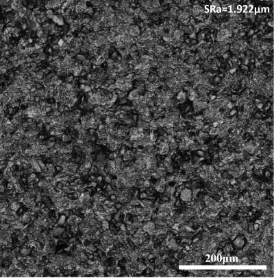
Fig. 1. Alumina ceramics gear surface
Table 1. Main parameters of the test material
| Parameter | Value |
|---|---|
| Main material components | Al2O3≥99% |
| Density | 3.85 g·cm-3 |
| Hardness | 1700 HV |
| Compressive strength | 2500 MPa |
| Flexural strength | 310 MPa |
| Fracture toughness | 4 MPa m1/2 |
| Young’s modulus | 360 GPa |
| Poisson ratio | 0.23 |
| Tensile strength | 550 MPa |
| Sintering temperature | 1690 ℃ |
2.2 Processing and Testing Instruments
The laser processing system used in this paper is shown in Fig. 2a. The system (BC-2900) is equipped with an infrared ultrashort pulsed picosecond laser developed and produced by LinitiaLase (China), which emits a flat-top (Top-Hat) beam profile. The main technical parameters of the laser are shown in Table 1. The movement and rotation of the workpiece fixture are computer-controlled to ensure precise positioning during laser processing. The 3D laser scanning microscope LEXT OLS5000, Olympus, (Japan) shown in Fig. 2b can perform sub-micrometer 3D surface measurements and was used to observe the surfaces of the test samples and to measure and extract relevant experimental data.
Table 2. Key technical specifications of infrared picosecond laser
| Parameter | Value |
|---|---|
| Central wavelength | 1028±5 mm |
| Maximum output power | 10 W |
| Maximum pulse energy | 200 μJ |
| Laser frequency | 1 kHz to 200kHz |
| Beam divergence | < 20 μrad |
| Beam quality | < 1.2 |
| Beam diameter | 30 μm |
2.3 Experimental Design
2.3.1 Gear Laser Polishing Method
To ensure complete laser coverage of the tooth surface, avoid interference with the gear geometry, and minimize laser energy loss, the gear was placed at a position where the axis of symmetry axis formed an angle of 46.35° with respect to the laser beam, which was analyzed through computer-aided design (CAD) software. Because effective laser ablation cannot be achieved when the focal position deviates significantly from the focal plane, the processed tooth surface was divided into several small processing areas along the involute tooth profile and machined sequentially. Prior to processing each region, the laser focus was adjusted to the center of the mesh. During machining, the gears were mounted on a three-jaw fixture on the laser stage, while the rotational angle of the gear as well as the vertical movement of the laser galvanometer were controlled using a computer-controlled system as shown in Figs. 2c and 2d.
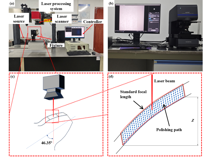
Fig. 2. Experimental instruments and processing methods; a) laser processing system, b) 3D laser scanning microscope, c) and d) polishing methods and localized schematic diagram
2.3.2 Exploration of Tooth Surface Processing Grid and Its Influencing Factors
To balance processing efficiency and processing effect, the number of processing grids should be reduced during partitioning. Therefore, it is necessary to determine the maximum allowable processing grids size of the processing method. Restrictions on the size of the processing grid is mainly governed by the loss of surface spot energy density across the tooth surface. As the distance from the grid center increases, the absorbed energy density gradually decreases. When the ablation depth appears to decline, the corresponding grid size is considered to exceed the maximum size of the processing grid, as shown in Fig. 2d. In this study, the vertical span Z was defined as the quantitative parameter used to characterize the size of the processing grid.
As the laser produces a spot diameter of only 30 μm on the tooth surface, and the scanning line spacing does not exceed its spot diameter, both dimensions are much smaller than the overall geometry of the gear. Under these conditions, the local processing area can be reasonably approximated as a planar surface. Therefore, an inclined planar specimen was employed to investigate the maximum allowable processing grid size (Z) permitted by the laser processing platform. Specifically, oblique laser scanning was performed over the region with a vertical span of 10 mm, which is significantly larger than the allowable focal offset. By observing the ablation depth within the inclined ablation region, as shown in Fig. 3, the maximum width of the flat ablation area W was measured. The corresponding maximum allowable processing grid size Z, defined as the maximum effective machining area, was then calculated using Eq. (1). Using a single variable control approach, the influence of laser incidence angle, scanning line spacing, and number of scans on the processing grid size were investigated.
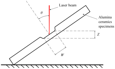
Fig. 3. Maximum size test method for processing grids
In several previous studies, the processing approach involved dividing the surface into multiple grids and machining each grid sequentially, while maintaining a fixed processing position for multiple scans, as shown in Fig. 4a. In order to minimize the error of the focal offset distance (FOD) and beam incidence angle (BIA) of the incoming band accumulating at the splice joints [28], the processing method in this paper adopts a cross-stacked scanning strategy, as shown in Fig. 4b. The detailed comparison between the two stacked scanning methods is discussed in Section 3.2. According to the maximum processing grid size obtained from the preceding experiments, the tooth surface was partitioned into a number of Z-axis spanning 0.5 mm grids, with the gear axis center as the O-point. The coordinates in the XZ plane are shown in Table 3.
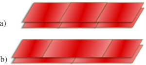
Fig. 4. Schematic diagram of the scanning mode of processing grid superposition; a) repeated scanning of a single grid, and b) cross-stacked scanning of A-B grid
Table 3. Grid coordinates
| Mesh A | Mesh B | |||
|---|---|---|---|---|
| X | Z | X | Z | |
| 19.96 | 22.4 | 19.96 | 22.4 | |
| 18.53 | 21.91 | 19.17 | 22.15 | |
| 17.44 | 21.41 | 17.98 | 21.67 | |
| 16.59 | 20.91 | 17.04 | 21.19 | |
| 15.93 | 20.41 | 16.28 | 20.69 | |
| 15.45 | 19.94 | 15.7 | 20.21 | |
| 14.98 | 19.44 | 15.24 | 19.71 | |
| 14.2 | 19.01 | 14.69 | 19.21 | |
| 13.38 | 19.02 | 13.83 | 18.97 | |
| 13.38 | 19.02 | |||
2.3.3 Optimization of Laser Polishing Parameters
Picosecond pulse laser is a high-energy, high-frequency light source whose main parameters include the average power P [W], repetition frequency f [kHz], scanning speed v [mm/s], scanning line spacing d [mm], and number of scans n. As shown in Fig. 5, this processing principle is based on high-precision scanning technology, wherein the laser beam forms a directional spot on the workpiece surface upon activation. During this process, the energy E of a single laser spot is calculated using Eq. (2), while the spot overlap ratio η is calculated using Eq. (3). The laser spot power density Φ is given by Eq. (4), where D represents the spot diameter.
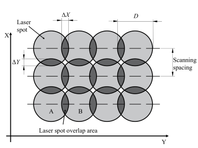
Fig. 5. Principle of picosecond pulsed laser scanning
To explore the influence of individual processing parameters on the surface roughness of alumina ceramics and to determine preliminary processing parameters, surface roughness was selected as the response target. Four laser process parameters, namely laser power, gap of laser scanning path, scanning speed, and number of scans, were considered as the influencing factors. The levels of the four process parameters are shown in Table 4. According to the experimental principle of Taguchi method, an L16 (44) orthogonal array comprising 4 factors at 4 levels was designed, shown in Table 5. Factors A, B, C and D represent the laser power, scanning spacing, scan speed, and number of scans, respectively. The corresponding results measured experimentally are shown in Table 6.
Table 4. Factors and their levels
| Level | Factor | |||
|---|---|---|---|---|
| A Laser power [W] |
B Scanning spacing [μm] |
B Scan speed [mm/s] |
D Number of scans [-] |
|
| 1 | 10 | 5 | 100 | 1 |
| 2 | 8 | 10 | 200 | 3 |
| 3 | 6 | 20 | 300 | 5 |
| 4 | 4 | 30 | 400 | 7 |
Table 5. L16(44) Taguchi orthogonal experimental design
| No | A | B | C | D | Number | A | B | C | D |
|---|---|---|---|---|---|---|---|---|---|
| 1 | 10 | 5 | 100 | 1 | 9 | 6 | 5 | 300 | 7 |
| 2 | 10 | 10 | 200 | 3 | 10 | 6 | 10 | 400 | 5 |
| 3 | 10 | 20 | 300 | 5 | 11 | 6 | 20 | 100 | 3 |
| 4 | 10 | 30 | 400 | 7 | 12 | 6 | 30 | 200 | 1 |
| 5 | 8 | 5 | 200 | 5 | 13 | 4 | 5 | 400 | 3 |
| 6 | 8 | 10 | 100 | 7 | 14 | 4 | 10 | 300 | 1 |
| 7 | 8 | 20 | 400 | 1 | 15 | 4 | 20 | 200 | 7 |
| 8 | 8 | 30 | 300 | 3 | 16 | 4 | 30 | 100 | 5 |
Table 6. Results of orthogonal experiment
| No | Surface roughness [μm] | No | Surface roughness [μm] |
|---|---|---|---|
| 1 | 1.762 | 9 | 1.462 |
| 2 | 1.752 | 10 | 1.591 |
| 3 | 2.375 | 11 | 2.843 |
| 4 | 3.257 | 12 | 2.286 |
| 5 | 1.802 | 13 | 2.012 |
| 6 | 1.634 | 14 | 2.236 |
| 7 | 2.594 | 15 | 1.993 |
| 8 | 2.363 | 16 | 2.209 |
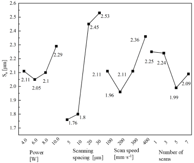
Fig. 6. Orthogonal test for each factor level means
The experimental data presented in Table 6 were analyzed using polar deviation analysis, and the plot of the mean values for each level of the factor is shown in Fig. 6. Based on Taguchi’s method, the optimal processing parameter combination was identified as A2B1C2D3 (laser power of 6 W, scanning spacing of 5 μm, scanning speed of 200 mm/s, and number of scans of 5). The optimal parameter set was subsequently used in additional verification experiments, yielding a surface roughness of 1.3 μm. In the subsequent experiments, this parameter combination was adopted as the baseline condition for future studies.
After determining the optimal parameters of gear laser processing, a control variable method was adopted to further refine each parameter. According to the experimental results of Taguchi method, scanning spacing and scanning speed were identified as the most influential factors affecting surface roughness. Accordingly, the interval between the scanning spacing levels was set to 2 μm, and the difference between the scanning speed levels was set to 20 mm/s. The detailed experimental parameters are listed in Table 7, with the pulse frequency fixed at 100 kHz. During laser processing, the gears were mounted on a three-grip caliper clamp on the laser processing platform. Different laser processing parameters were applied to irradiate and ablate defined regions on the gear tooth surfaces. To ensure the reliability and statistical significance of the experimental results, machining experiments were repeated on five distinct gear tooth surfaces for each combination of laser parameters. For each machined tooth surface, three random points were selected within its central region for surface roughness measurements, and the average value was taken serving as the final roughness value for that surface. Ultimately, the reported results represent the mean of the five independent tooth surface roughness values, with error bars denoting standard deviation (SD), expressed as mean ± SD. This approach objectively characterizes both the dispersion of data and the repeatability of the process. The experimental results and corresponding discussion are presented in Section 3.3.
Table 7. Laser processing experimental parameters
| Parameter | Value |
|---|---|
| Scanning spacing [μm] | 1, 3, 5, 7, 9 |
| Number of scans [-] | 1, 3, 5, 7, 9 |
| Scanning speed [mm/s] | 160, 180, 200, 220, 240 |
| Laser power [W] | 5, 6, 7, 8, 9 |
3 RESULTS AND DISCUSSION
3.1 Analysis of Factors Affecting the Size of the Processing Grid
To explore the influencing factors of the maximum size of the processing grid mesh, oblique ablation experiments were conducted. The results measured by laser confocal microscopy are shown in supplementary material in Fig. S1, and the trends are summarized in Fig. 7. To ensure clear and comparable experimental results, a set of basic parameters were selected: laser power of 6 W, scanning spacing of 5 μm, scanning speed of 200 mm/s, number of scanning times 10, and the laser angle of 30°. Under these conditions, a rectangular area was ablated on an inclined surface. Subsequently, the laser incidence angle, number of scans, and the scanning spacing were varied. The resulting maximum processing grid widths were then compared to analyze the effect of different parameters on the dimensions of the processing grid.
Under ideal conditions, the processing grid widths measured at different laser incidence angles should exhibit identical vertical coordinate differences after trigonometric transformation. However, the experimental results indicate that with the decrease of the laser incidence angle (θ), the maximum size of the processing grid increases. This behavior can be attributed to changes in the laser geometry on the workpiece surface. As the incidence angle decreases, the circular laser spot irradiated on the surface of the workpiece gradually distorted into elliptical shape. In this case the short axis length S remains equal to the original spot diameter, while the length of the long axis is defined by Eq. (5). The energy density (Φθ) at an incidence angle of θ is obtained from Eq. (6).
This distortion of the laser spot geometry further leads to a reduction in the energy density of an individual laser spot. When the beam deviates from the standard vertical distance of z, the spot size expands linearly. For small laser dispersion angle α, the corresponding spot energy density Φ’θ is expressed by Eq. (7). By comparing Eqs. (5) and (6) the variation in energy density caused by the combined effects of incidence angle and focal offset can be derived. The resulting difference between the energy density at a focal offset z and that at the nominal focal position, denoted as ∆Φθz is shown in Eq. (8).
Since E, S, α are are independent of the incidence angle θ, then terms (4E cosθ)/(π S2) = k, (4E cosθ) / (π(S+zα)2) = k’, can be defined as constants k and k′, respectively. Substituting these expressions into Eq. (8) yields Eq. (9). The decrease of spot energy density with the offset distance z is strongly depended on θ. Specifically, as the angle of incidence increases, the rate of energy density decay with z, can be defined as constants k and k′, respectively. Substituting these expressions into Eq. (8) yields Eq. (9). Consequently, a larger angle of incidence results in a smaller allowable span in the Z-axis direction, thereby reducing the maximum permissible size of the processing grid.
By combining the results shown in Fig. S1 and Fig. 7, it can be found that the maximum size of the processing grid area decreases with an increasing number of scans and with decreasing scanning line spacing. This behavior arises because, during laser scanning, the number of times a unit area is irradiated by the laser spot is jointly determined by the number of scans and scanning spacing. When a surface location is irradiated n times, the total energy density Φn of the absorbed laser light per unit area is determined by Eq. (10). It can be seen that the total energy density Φnz at the perpendicular distance z from the standard focal length is given by Eq. (11), and the energy difference with the standard focal length is expressed by Eq. (12). It is evident that, at a fixed vertical offset distance, ∆Φnz increases increasing vertical offset distance z. As a result, the effective processing capability decreases more rapidly as the number of scans increases and the scanning spaces decreases. The effect of each laser processing parameter on the processing grid size observed experimentally in Fig. 7 are in good agreement with the theoretical predictions derived from Eq. (12). Taking into account both effects, the influence of the laser parameters and the positioning accuracy of the laser platform, the maximum processing grid size in the Z-axis direction was ultimately restricted to a span of 500 μm.
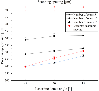
Fig. 7. Effect of different parameters on the dimensions of the processing grid
3.2 Effect of Processing Grid Superposition Method on the Machined Surface
As mentioned in Eq. (8), as the laser irradiation position deviates from the standard focal plane by distance z, the laser spot gradually diverges, resulting in a reduction of energy density by ∆Φθz. During gear machining, the variation in the slope of the tooth profile is relatively small. Experimental results presented in Section 3.1 show that, within a standard focal range of ±0.25 mm, the loss of energy density is dominated mainly by focal length shift. Accordingly, the tooth surface in this study was divided into a uniform 0.5 mm Z-axis span. Therefore, when repeated laser scanning is performed using the conventional superimposed grid strategy shown in Fig. 5a, the total energy density at the center of the processing grid is denoted as Φn, whereas the total energy density at the splicing area of the processing grid is Φn0.25. This difference in accumulated energy density causes processing errors to accumulate at the splicing area of the grids, leading to uneven material removal, degradation of the quality of the tooth-face machining, and abrupt variations in the tooth profile. In contrast, when the grids are cross-stacked, both the total energy density at the center and the edge of the processing grid can be described uniformly by Eq. (13). Under shallow ablation conditions, the total energy density at these two locations becomes approximately equal, resulting in a more uniform energy distribution across the tooth surface.
Figs. S2 and S3 compare the effects of the two superimposed scanning methods on the surface morphology of the tooth splice region. The experimental results show that, when conventional single-area repeated scanning method is used (Fig. S2), a crease-like protrusion transversely extending across the tooth surface forms at the splice joint. This effect arises from insufficient cumulative laser energy density after five repeated scans, resulting in an abrupt change in the local curvature of the tooth profile. In contrast, the A-B dual-area cross-stacked scanning method (Fig. S3), achieves a smooth transition of the tooth profile curve by adjusting the laser energy distribution uniformly across the tooth surface, and no obvious morphological defects are observed. Considering the high melting point and thermal stability of alumina ceramics, the differences observed in surface morphology are mainly attributed to the variability of laser energy density distribution. The theoretical energy density calculations based on Eqs. (12) and (13) further show that the cross-stacked scanning strategy effectively reduces energy density differences in the splicing region, thus suppressing the generation of processing errors.
3.3 Optimization of Laser Parameters
Alumina ceramics exhibit high hardness and thermal stability, with a melting point of approximately 2050 °C. As a result, effective material removal during laser ablation relies primarily on high-energy transient heating and thermal shock effects, making the process highly sensitive to the laser energy distribution. Due to the mechanical processing of alumina ceramics gear samples, material removal occurs predominantly through brittle fracture of the surface material, resulting in a higher number of micro-pits and micro-cracks on its surface. When laser polishing is applied using appropriate parameters, it produces a slight abrasion of the surface when it removes the material from the rough surface uniformly. Simultaneously, the process of fusion and recrystallization fills up the pits and cracks, thus making the tooth surface smoother.
The scanning spacing determines the spot overlap rate ΔY in Y-direction, and the effect of scanning spacing on tooth surface morphology and roughness is shown in Fig. S4 under fixed conditions (power of 6 W, scanning speed of 200 mm/s, and number of scans 5). As shown in Fig. 8, as the scanning pitch increases, the surface roughness shows a trend of first decreasing and then increasing. When the scanning pitch was too small, ΔY increased, resulting in repeated laser irradiation per unit area. As the scanning spacing is increased to 5 μm, surface asperities are uniformly removed through coordinated material ablation and reflow, and the surface roughness Sa decreases to 1.659 μm. As the scanning spacing increases, the material removal efficiency decreases, and surface protrusions and depressions on the surface cannot be removed efficiently, causing the Sa to increase to 1.998 μm. The combination of the morphology observation and roughness measurement data shows that the optimal surface quality is achieved at a scanning spacing of 5 μm.
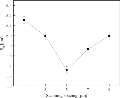
Fig. 8. Surface roughness trend with scanning spacing
The number of scans determines how many times the macroscopic tooth surface is subjected to laser processing. After a single scan, the laser-irradiated surface cools rapidly and solidifies before the subsequent scan. As a result, increasing the number of scans may lead to re-ablation of an already smoothed surface. The effect of scanning speed on tooth surface morphology and roughness is shown in Fig. S5 (power of 6 W, scanning speed of 200 mm/s, scanning spacing of 5 μm). As shown in Fig. 9, as the number of scans increases from 1 to 9, the surface roughness decreases to 1.434 μm. When only 1 scan is applied, the amount of material removed is insufficient to eliminate the height differences between surface asperities, and the molten material cannot effectively fill the craters. Consequently, the pre-ablative surface morphology remains partially visible. When the number of scans is increased to 3, surface protrusions are effectively removed, while molten material flows into the pits, resulting a surface with Sa of 1.434 μm. However, as the number of scans further increased to 9, repeated laser irradiation leads to the formation of ablation traces on the previously smoothed surface, causing the surface roughness to increase again. Summarizing the above results, the processing effect is most satisfactory when the scanning number is set to 3.
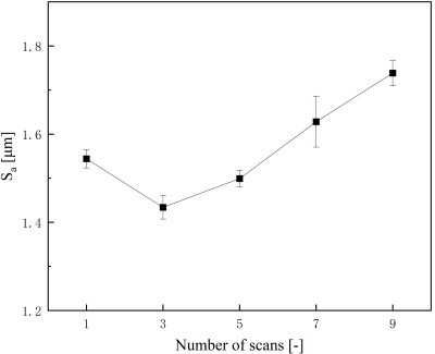
Fig. 9. Surface roughness trend with the number of scans
Scanning speed determines the duration for which the laser beam acts on a unit area. As the scanning speed increases, the spot overlap area ΔX in X-direction decreases, resulting in reduced laser energy absorbed by the surface material. The effect of scanning speed on tooth surface morphology and roughness is shown in Fig. S6 (power of 6 W, scanning number of 3, scanning spacing of 5 μm). In this experiment, the Sa exhibited only moderate sensitivity to changes in scanning speed. As the scanning speed gradually increased from 160 mm/s to 220 mm/s, Sa decreased from 1.371 μm to 1.195 μm, and then increased to 1.212 μm when it was further increased to 240 mm/s. This is due to the fact that at a scanning speed of 160 mm/s, the prolonged laser-material interaction time causing nonuniform ablation and material distribution. This results in uneven material ablation and thus increased surface roughness. Conversely, at an increased scanning speed to 240 mm/s, ΔX becomes too small, again producing uneven energy distribution and insufficient material removal, resulting in an increase of surface roughness. Combining the above experimental results, the optimal scanning speed for laser polishing of alumina ceramics gears is 220 mm/s.
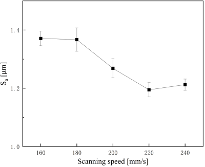
Fig. 10. Surface roughness trend with scanning speed
Laser power is an important parameter for micromachining with picosecond pulsed lasers, which directly affects the energy delivered by a single spot. The effect of the number of scans on the tooth surface morphology and roughness is shown in Fig. S7 (the number of scans is 3, the scanning speed is 200 mm/s, and the scanning spacing is 5 μm). When the laser power is too low, the spot energy density falls below the ablation threshold of the material, preventing effective ablation of the material. As the laser power is increased from 5 W to 9 W, Sa first decreases from 1.286 μm to 1.156 μm. And when the laser power is further increased to 9 W, Sa increases to 1.447 μm. At this higher power level, excessive energy input intensifies material vaporization and melting, leading to over-ablation. Summarizing the results of the above experiments, the tooth surface obtained from the processing is most ideal when the laser power is 7 W.
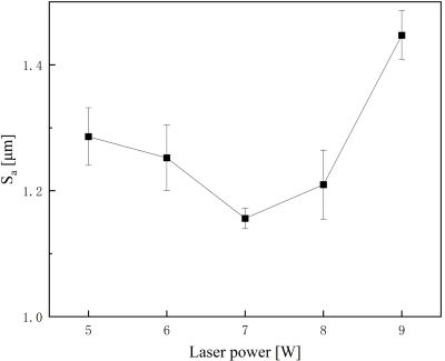
Fig. 11. Surface roughness trend with laser power
In summary, the optimal laser processing parameter combination obtained in this study consists of a laser power of 7 W, a scanning spacing of 5 μm, a scanning speed of 220 mm/s, and a number of scans set to 4. Compared with the optimal parameter combination obtained using the Taguchi methodology in Section 2.3.2 (laser power of 6 W, scanning spacing of 5 μm, scanning speed of 200 mm/s, and number of scans set to 5 times), only minor differences are observed. These discrepancies arise because the Taguchi matrix parameter settings did not include the 6 W and 220 mm/s values employed in this combination. As demonstrated in Fig. 6, the optimal parameter combination obtained in this section aligns with the overall variation patterns derived from the Taguchi method, confirming the reliability and validity of the selected processing conditions.
Considering the processing error problem described in Section 3.2, an even number of scans was selected to compensate for the processing error caused by the surface energy differences. Based on the analysis shown in Fig. 12, the number of scans was therefore set to 4. Therefore, the final optimal laser parameters determined in this study are a laser power of 7 W, a scanning spacing of 5 μm, a scanning speed of 220 mm/s, and 4 scans. After multiple experimental verifications, the resulting surface of this parameter combination was compared with the original gear surface as shown in Fig. 8. Compared with the original surface (Sa of 1.922 μm), laser polishing effectively removed the spike- and depression-like morphology formed by brittle material removal. As a result, a relatively smoother tooth surface was obtained, with an average Sa of 1.091 μm with an error range determined at ±0.025 μm. This corresponds to a reduction in surface roughness of 41.93 % to 44.53 %.
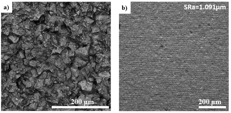
Fig. 12. a) Original tooth surface of the gear (1126×), and b) topography of the tooth surface after laser treatment (454×)
3.4 Relationship Between Laser Energy Input and Surface Evolution
To establish a quantitative relationship between the laser processing parameters and surface phase transitions, a simplified thermal model is introduced to estimate the surface temperature rise induced by laser irradiation. This model assumes that laser energy is absorbed at the material surface and converted into thermal energy, which is subsequently utilized to elevate the temperature of a surface layer with a thickness equal to the thermal diffusion depth.
The single pulse energy Ep is calculated as Ep = P / f, where P is the average power and f is the laser frequency. The spot area S = π(D/2)², where D denotes the laser spot diameter. The peak power density Φp is defined as:
where τ denotes the pulse width, the thermal diffusion depth δ is calculated as δ= α⋅τ, where α represents the thermal diffusion coefficient of aluminum oxide. The volume of the heated material is expressed as V = S⋅δ.
The surface temperature rise ΔT is estimated by the following equation:
where A denotes the material’s absorption coefficient for laser radiation, p represents the density of aluminum oxide, and c signifies the specific heat capacity.
Combining the aforementioned equations yields:
The proposed thermal model was employed to calculate the temperature rise per pulse under optimal process parameters. The calculated parameters, including single-pulse energy, spot area, peak power density, and thermal diffusion depth, were substituted into the temperature rise equation. The resulting temperature increase was found to significantly exceed the melting point of aluminum oxide, indicating that a single pulse is sufficient to induce surface melting. However, owing to the pulse’s extremely short duration, the heat-affected zone remains minimal. The rapid melting and subsequent solidification of the surface material enable precise material removal and a smooth surface finish.
3.5 Effect of Laser Polishing on Tooth Performance
During the laser treatment of alumina ceramics gear teeth, in addition to direct surface material removal by the laser, the laser-induced thermal effects can also cause phase changes, grain structure changes, chemical composition changes and other behaviors, which usually cause changes in the physical properties of the material surface. Therefore, to verify the effect of laser surface treatment on the surface properties of alumina ceramics gears, Vickers hardness tests were conducted on the tooth surface before and after laser treatment. Since the mechanical properties of alumina ceramics are sensitive to sintering temperature, variations between different specimen materials could affect the experimental results. To minimize such effects and ensure reliable comparisons, hardness measurements were performed on the same gear and the same tooth surface. Each tooth surface was divided into left and right areas, 10 measurement points were selected in each region, for measurement, and the average value was calculated, in order to maximize scientific rigor and accuracy of the conclusions.
The results of the surface microhardness tests conducted under a load of 1 kg are shown in Fig. 13. Prior to laser processing, the original tooth surface was polished to facilitate clear observation of the indentation morphology. The results show that the Vickers hardness of the alumina ceramics gear tooth surface increased from 1965.33 HV to 2090.242 HV after laser treatment, corresponding to an improvement of 6.36 % relative to the original surface. Since these experimental results were measured on the same tooth surface, the effect caused by the sintering temperature can be excluded. Therefore, the observed increase in hardness can be attributed to the laser-induced effect. Under laser irradiation, a part of the material reaches the ablation threshold, resulting in slight ablation accompanied by localized melting. Subsequent recasting and recrystallization refined the surface microstructure, producing more homogeneous and densely bonded grains. The microstructural changes enhance surface resistance to localized deformation (i.e., diamond indenters), which is manifested as an increase in surface hardness.
To investigate the effect of laser-induced surface property modifications on resistance to localized loads, high-load damage tests were conducted using a diamond Vickers hardness indenter. The material’s resistance to localized stress concentration was evaluated by observing its indentation-induced damage behavior. Fig. 14 shows the comparison of indentation morphology characteristics of the tooth surface subjected to a load of 10 kg. The experimental results show that, under a 10 kg load, the original tooth surface exhibits not only plastic deformation characteristics but also pronounced brittle fracture in the stress concentration areas along the diagonal direction of the indentation. In addition, an obvious material bulging morphology is observed at the edges of the indentation. This behavior originates from the propagation and coalescence of pre-existing micro-cracks under the localized high stresses, ultimately leading to surface material spalling and failure. In contrast, the laser-strengthened tooth surface shows a complete and regular indentation morphology, with no observable crack propagation and edge spalling. This significant difference in morphology indicates that, on the one hand, the flattening of the surface increases the microscopic contact area, promoting the more uniform local load distribution and reducing the microscopic stress concentration, thereby suppressing brittle fracture of the material. On the other hand, laser-induced surface treatment effectively improves the damage resistance of the material. Through the role of surface reinforcement, laser treatment enhances the brittle fracture resistance of the tooth face under the localized contact load, which effectively inhibits the suppressed occurrence of tooth flank spalling failure.
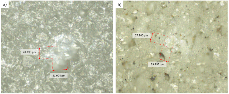
Fig. 13. a) Microhardness of original tooth surface, and b) microhardness of tooth surface after laser polishing
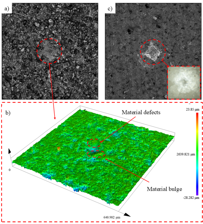
Fig. 14. Indentation morphology under 98 N load a) original surface indentation morphology, b) 3D morphology of original tooth indentation, and c) indentation morphology after laser polishing
During gear transmission, tooth surfaces are primarily subjected to normal loads and frictional forces. Due to the hard and brittle nature of alumina ceramics, needle-like protrusions are readily formed on the tooth surfaces during mechanical forming and manufacturing processes. During meshing under load, these protrusions come into contact with the opposing tooth surface, leading to microscopic stress concentration. As transmitted load and rotational speed increase, these protrusions are prone to fracture risks, potentially triggering tooth surface spalling failure. Following laser surface treatment, the shedding of tooth surface peaks and valleys is significantly reduced, resulting in smoother tooth surface. Compared with the original tooth surface, laser treatment increases the microscopic contact area under external loading, thereby mitigating micro-stress concentrations. Simultaneously, enhanced resistance to localized loading further reduces brittle fracture during meshing, lowering the risk of tooth surface defect failure. In summary, laser surface treatment effectively improves the meshing performance of load-bearing reliability of alumina ceramic gears.
4 CONCLUSION
To improve the surface quality of alumina ceramics gears, this study proposes a method of tooth surface polishing using an ultrashort pulse laser. The laser energy distribution during tooth surface processing was systematically analyzed, the sources and influencing factors of processing-induced errors were identified, and these errors were effectively compensated by optimizing the superimposed scanning method of the processing grid. The results are summarized as follows.
(1) Deviation of the laser interaction from the focal length of the galvanometer leads to nonuniform energy absorption on the tooth surface. An increase in laser incidence angle and the number of scans, as well as a decrease in scanning spacing, exacerbate this imbalance and reduce the maximum allowable processing grid size. Under processing conditions of 6 W, 200 mm/s, 5 scans and 5 μm, the maximum size allowed was determined to be 500 μm.
(2) An alternating superposition of laser processing grids on the tooth surface compensates for uneven energy distribution phenomenon generated by the laser focal length shift and incidence angle shift. This approach significantly reduces the protruding morphology at the junction and improves the overall processing quality of the tooth surface.
(3) Univariate experiments were conducted to determine the optimal parameters for scanning spacing, number of scans, scanning speed, and laser power. Using the optimized parameter combination (7 W, 220 mm/s, number of scans of 4, scanning spacing of 5 μm), the tooth surface roughness Sa was reduced by 43.24 %, from 1.922 μm to 1.091 μm.
(4) A quantitative relationship between laser energy input and surface evolution was established through a simplified thermal model. This model quantitatively demonstrates that picosecond lasers can melt a thin surface layer during each pulse, achieving uniform material removal and surface smoothing through multiple scans. Furthermore, the model explains the phenomenon of increased surface roughness at excessively high energy inputs, arising from over-vaporization and molten material splattering.
(5) Laser surface treatment increased the surface microhardness of alumina ceramics gears increased by 6.36 % and enhanced resistance to localized high-loads. Moreover, the smoother tooth surface reduces microscopic stress concentration and improves the meshing performance of alumina ceramics gears. This method is applicable to various cylindrical surfaces and other precision components featuring complex curved surfaces. Furthermore, it offers high automation levels, high efficiency and low energy consumption, presenting considerable application potential and value in industrial production.
References
[1] Zhai, W., Bai, L., Zhou, R., Fan, X., Kang, G., Liu, Y. et al. Recent Progress on Wear-Resistant Materials: Designs, Properties, and Applications. Adv Sci 8 2003739 (2021) DOI:10.1002/advs.202003739.
[2] Chate, G.R., Kulkarni, R.M., Nikhil, N.R., Chate, V.R., Patel, M.G.C., Sollapur, S. Ceramic material coatings: emerging future applications. Adv Ceram Coat Emerg App 3-17 (2023) DOI:10.1016/B978-0-323-99624-2.00007-3.
[3] Parveez, B., Kittur, M.I., Badruddin, I.A., Kamangar, S., Hussien, M., Umarfarooq, M.A. Scientific advancements in composite materials for aircraft applications: A Review. Polymers 14 5007 (2022) DOI:10.3390/polym14225007.
[4] Duan, J., Zhang, M., Chen, P., Li, Z., Pang, L., Xiao, P. et al. Tribological behavior and applications of carbon fiber reinforced ceramic composites as high-performance frictional materials. Ceram Int 47 19271-19281 (2021) DOI:10.1016/j.ceramint.2021.02.187.
[5] Huang, R., Deng, J., Ma, X., Mao, Y., Fan, S. Modifying C/C-SiC brake pads with different Fe-Si alloy phases to improve the wear resistance of full-carbon/ceramic brake pair. Ceram Int 50 10582-10592 (2024) DOI:10.1016/j.ceramint.2023.12.370.
[6] Vasileiou, G., Rogkas, N., Markopoulos, A., Spitas, V. Fully ceramic versus steel gears: Potential, feasibility and challenges. Proc Inst Mech Eng C-J Mech Eng Sci 238 775-784 (2024) DOI:10.1177/09544062231198633.
[7] Zhang, L., Zeng, Y., Yao, H., Shi, Z., Chen, J. Fabrication and characterization of ZrO2(3Y)/Al2O3 micro-ceramic gears with high performance by vat photopolymerization 3D printing. Ceram Int 50 5187-5197 (2024) DOI:10.1016/j.ceramint.2023.11.264.
[8] Dhanasekar, S., Ganesan, A.T., Rani, T.L., Vinjamuri, V.K., Nageswara Rao, M., Shankar, E. et al. A comprehensive study of ceramic matrix composites for space applications. Adv Mater Sci Eng 2022 6160591 (2022) DOI:10.1155/2022/6160591.
[9] Buj-Corral, I., Tejo-Otero, A. 3D printing of bioinert oxide ceramics for medical applications. J Funct Biomater 13 155 (2022) DOI:10.3390/jfb13030155.
[10] Soboyejo, W.O., Obayemi, J.D., Annan, E., Ampaw, E.K., Daniels, L., Rahbar, N. Review of high temperature ceramics for aerospace applications. Adv Mater Res 1132 385-407 (2015) DOI:10.4028/www.scientific.net/AMR.1132.385.
[11] Sharma, A., Babbar, A., Tian, Y., Pathri, B.P., Gupta, M., Singh, R. Machining of ceramic materials: a state-of-the-art review. Int J Interact Des Manuf 17 2891-2911 (2023) DOI:10.1007/s12008-022-01016-7.
[12] Ibrahim, A., Papini, M. Controlled depth micro-abrasive waterjet milling of aluminum oxide to fabricate micro-molds containing intersecting free-standing structures. Precis Eng 75 24-36 (2022) DOI:10.1016/j.precisioneng.2022.01.007.
[13] Li, C., Li, T., Zhang, X., He, T., Su, L., Wen, D. et al. Investigating the influence of laser-etched straight and wavy textures on grinding efficiency and tool quality of WC-Co carbide cutting tools. Materials 18 528 (2025) DOI:10.3390/ma18030528.
[14] Zhang, X., Zhang, R., Wen, D., Chen, X., Li, C., Ding, Y. et al. Experimental study of picosecond laser-assisted grinding of GH4169 nickel-based superalloy. Mater Today Commun 40 110069 (2024) DOI:10.1016/j.mtcomm.2024.110069.
[15] Wang, Q., Zhang, R., Chen, Q., Duan, R. A review of femtosecond laser processing of silicon carbide. Micromachines (Basel) 15 639 (2024) DOI:10.3390/mi15050639.
[16] Wang, H., Deng, D., Zhai, Z., Yao, Y. Laser-processed functional surface structures for multi-functional applications-a review. J Manuf Process 116 247-283 (2024) DOI:10.1016/j.jmapro.2024.02.062.
[17] Zhang, X., He, T., Wen, D., Li, T., Chen, X., Li, C. et al. Improving zirconia ceramics grinding surface integrity through innovative laser bionic surface texturing. Ceram Int 50 32081-32097 (2024) DOI:10.1016/j.ceramint.2024.06.012.
[18] Kim, S.H., Sohn, I.-B., Jeong, S. Ablation characteristics of aluminum oxide and nitride ceramics during femtosecond laser micromachining. Appl Surf Sci 255 9717-9720 (2009) DOI:10.1016/j.apsusc.2009.04.058.
[19] Feng, J., Wang, J., Liu, H., Sun, Y., Fu, X., Ji, S. et al. A review of an investigation of the ultrafast laser processing of brittle and hard materials. Materials 17 3657 (2024) DOI:10.3390/ma17153657.
[20] Orazi, L., Romoli, L., Schmidt, M., Li, L. Ultrafast laser manufacturing: from physics to industrial applications. CIRP Annals 70 543-566 (2021) DOI:10.1016/j.cirp.2021.05.007.
[21] De Zanet, A., Casalegno, V., Salvo, M. Laser surface texturing of ceramics and ceramic composite materials – A review. Ceram Int 47 7307-7320 (2021) DOI:10.1016/j.ceramint.2020.11.146.
[22] Zhang, X., Ji, L., Zhang, L., Wang, W., Yan, T. Polishing of alumina ceramic to submicrometer surface roughness by picosecond laser. Surf Coat Techol 397 125962 (2020) DOI:10.1016/j.surfcoat.2020.125962.
[23] Ma, C.P., Guan, Y.C., Zhou, W. Laser polishing of additive manufactured Ti alloys. Opt Lasers Eng 93 171-177 (2017) DOI:10.1016/j.optlaseng.2017.02.005.
[24] Yung, K.C., Zhang, S.S., Duan, L., Choy, H.S., Cai, Z.X. Laser polishing of additive manufactured tool steel components using pulsed or continuous-wave lasers. Int J Adv Manuf Technol 105 425-440 (2019) DOI:10.1007/s00170-019-04205-z.
[25] Ahmed, N., Ahmad, S., Anwar, S., Hussain, A., Rafaqat, M., Zaindin, M. Machinability of titanium alloy through laser machining: material removal and surface roughness analysis. Int J Adv Manuf Tecnol 105 3303-3323 (2019) DOI:10.1007/s00170-019-04564-7.
[26] Mullick, S., Agrawal, A.K., Nath, A.K. Effect of laser incidence angle on cut quality of 4mm thick stainless steel sheet using fiber laser. Opt Laser Technol 81 168-179 (2016) DOI:10.1016/j.optlastec.2016.02.006.
[27] Hubeatir, K.A., AL-Kafaji, M.M., Omran, H.J. A review: Effect of different laser types on material engraving process. Res Rev: J Mater Sci 6 210-217 (2018) DOI:10.4172/2321-6212.1000235.
[28] Kumstel, J. Laser polishing of metallic freeform surfaces by using a dynamic laser beam preforming system. J Laser Appl 33 022020 (2021) DOI:10.2351/1.5128459.
[29] Ackerl, N., Warhanek, M., Gysel, J., Wegener, K. Ultrashort-pulsed laser machining of dental ceramic implants. J Eur Ceram Soc 39 1635-1641 (2019) DOI:10.1016/j.jeurceramsoc.2018.11.007.
[30] Batal, A., Michalek, A., Penchev, P., Kupisiewicz, A., Dimov, S. Laser processing of freeform surfaces: A new approach based on an efficient workpiece partitioning strategy. Int J Mach Tools Manuf 156 103593 (2020) DOI:10.1016/j.ijmachtools.2020.103593.
[31] Shukla, P.P., J. Lawrence, J. Fracture toughness modification by using a fibre laser surface treatment of a silicon nitride engineering ceramic. J Mater Sci 45 6540-6555 (2010) DOI:10.1007/s10853-010-4743-6.
[32] Shukla, P., Robertson, S., Wu, H., Telang, A., Kattoura, M., Nath, S. et al. Surface engineering alumina armour ceramics with laser shock peening. Mater Des 134 523-538 (2017) DOI:10.1016/j.matdes.2017.08.066.
[33] ISO 1328-1:2013, Cylindrical gears – ISO system of flank tolerance classification – Part 1: Definitions and allowable values of deviations relevant to flanks of gear teeth, International Standard Organization, Geneva (2013).